Refrigeration cycle system

A technology of refrigeration cycle and circulation system, applied in refrigerators, refrigeration components, refrigeration and liquefaction, etc., can solve the problem of low versatility and achieve the effect of improving versatility

Active Publication Date: 2016-12-14
MITSUBISHI ELECTRIC CORP
View PDF5 Cites 2 Cited by
  • Summary
  • Abstract
  • Description
  • Claims
  • Application Information

AI Technical Summary

Problems solved by technology

[0004] However, the conventional refrigeration cycle system described in Patent Document 1 has a structure in which two outdoor units are connected in parallel and two indoor units are connected in parallel through inter-unit piping, so the versatility is low.

Method used


Image

  • Refrigeration cycle system
  • Refrigeration cycle system
  • Refrigeration cycle system

Examples


Embodiment approach 1

[0024] Refrigeration cycle device

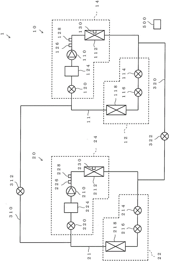
[0025] figure 1 It is a diagram schematically describing an example of the configuration of the refrigeration cycle system according to Embodiment 1 of the present invention. figure 1 The described refrigeration cycle system 1 is, for example, a system for air-conditioning the interior of buildings such as buildings and houses. The refrigeration cycle system 1 has a first refrigeration cycle device 10 , a second refrigeration cycle device 20 , and a first bypass passage 310 and a second bypass passage 320 connecting the first refrigeration cycle device 10 and the second refrigeration cycle device 20 . In addition, the refrigeration cycle system 1 includes a control device 500 that controls the entire refrigeration cycle system 1 . In addition, the control device 500 can also be installed in the first refrigeration cycle device 10 or the second refrigeration cycle device 20, and can also be composed of the control device (not shown) of the ...

Deformed example 1

[0084] Figure 7 is description figure 1 It is a diagram showing modified examples of the opening and closing timing of the operation mode valve and the timing of stopping and restarting the operation of the compressor when the high pressure of the refrigeration cycle system described is abnormal. Such as Figure 7 As shown, in Modification 1, the operation stop and restart of the first compressor 110 are performed using the determination pressure P1, and the first valve 312, the second valve 322, and the third valve 120 are set using the determination pressure P1-1. On and off state. The judgment pressure P1-1 is a value related to a pressure lower than the judgment pressure P1, and is a value at which the high pressure p1 is predicted to become higher than the judgment pressure P1 when the high pressure p1 rises above the judgment pressure P1-1. exist Figure 7 At time s11, when the high pressure p1 becomes higher than the determination pressure P1-1, the first valve 312...


PUM


Abstract

A refrigeration cycle system is provided with: a first refrigeration cycle device, wherein a first compressor, a first condenser, a first decompression device, and a first evaporator are connected, and a refrigerant is circulated; a second refrigeration cycle device, wherein a second compressor, a second condenser, a second decompression device, and a second evaporator are connected, and the refrigerant is circulated; a first bypass path that connects between the first evaporator and the first compressor, and between the second evaporator and the second compressor; and a second bypass path that connects between the first condenser and the first decompression device, and between the second condenser and the second decompression device. The first refrigeration cycle device also is provided with a third valve that is disposed between a first evaporator and a first compressor and is used for controlling flow of the refrigerant; and the second refrigeration cycle device also is provided with a fourth valve that is arranged between the second evaporator and the compressor and is used for controlling flow of the refrigerant; the first bypass connects the first evaporator to the third valve and the second evaporator to the fourth valve.

Description

technical field [0001] The present invention relates to a refrigeration cycle system having a first refrigeration cycle device and a second refrigeration cycle device. Background technique [0002] Conventionally, there is known an air conditioner in which two outdoor units are connected in parallel and two indoor units are connected in parallel through inter-unit piping including air pipes and liquid pipes (see Patent Document 1). In the conventional air conditioner described in Patent Document 1, when an abnormality or malfunction occurs in one of the outdoor units, the abnormal or malfunctioning outdoor unit is not operated, and the other outdoor unit that is normally operable is used for air-conditioning operation. . [0003] Patent Document 1: Japanese Patent Laid-Open No. 2007-127304 [0004] However, the conventional refrigeration cycle system described in Patent Document 1 has low versatility because it has a structure in which two outdoor units are connected in pa...

Claims


Application Information

Patent Timeline
Patent Type & Authority Applications(China)
IPC IPC(8): F25B1/10F25B41/04F25B49/02
CPCF25B1/10F25B49/02F25B41/20F25B41/22F25B41/24F25B5/02F25B6/02F25B2400/06F25B2400/075
Inventor 长江孝雄大矢亮
Owner MITSUBISHI ELECTRIC CORP
Why Eureka
Try Eureka