Autofocus method, device and imaging device

A technology of automatic focusing and imaging device, applied in focusing device, installation, image communication, etc., can solve the problems of mechanical movement of the camera, long focusing time, etc., to achieve the effect of multiple possibilities, convenience, and good user experience

Active Publication Date: 2019-03-19
成都微晶景泰科技有限公司
View PDF6 Cites 0 Cited by
  • Summary
  • Abstract
  • Description
  • Claims
  • Application Information

AI Technical Summary

Problems solved by technology

[0006] In view of this, the present invention provides an autofocus method, equipment, and imaging device to solve the problems in the prior art that autofocus requires mechanical movement of the camera and takes a long time to focus

Method used


Image

  • Autofocus method, device and imaging device
  • Autofocus method, device and imaging device
  • Autofocus method, device and imaging device

Examples


Embodiment approach 1

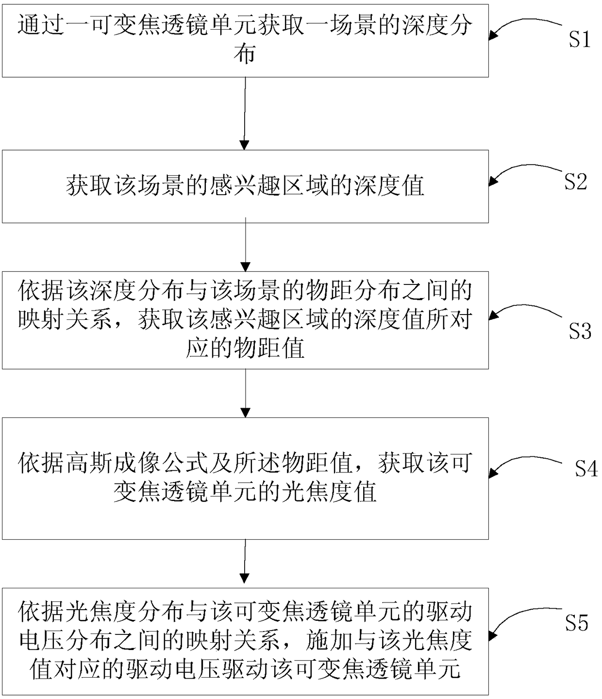
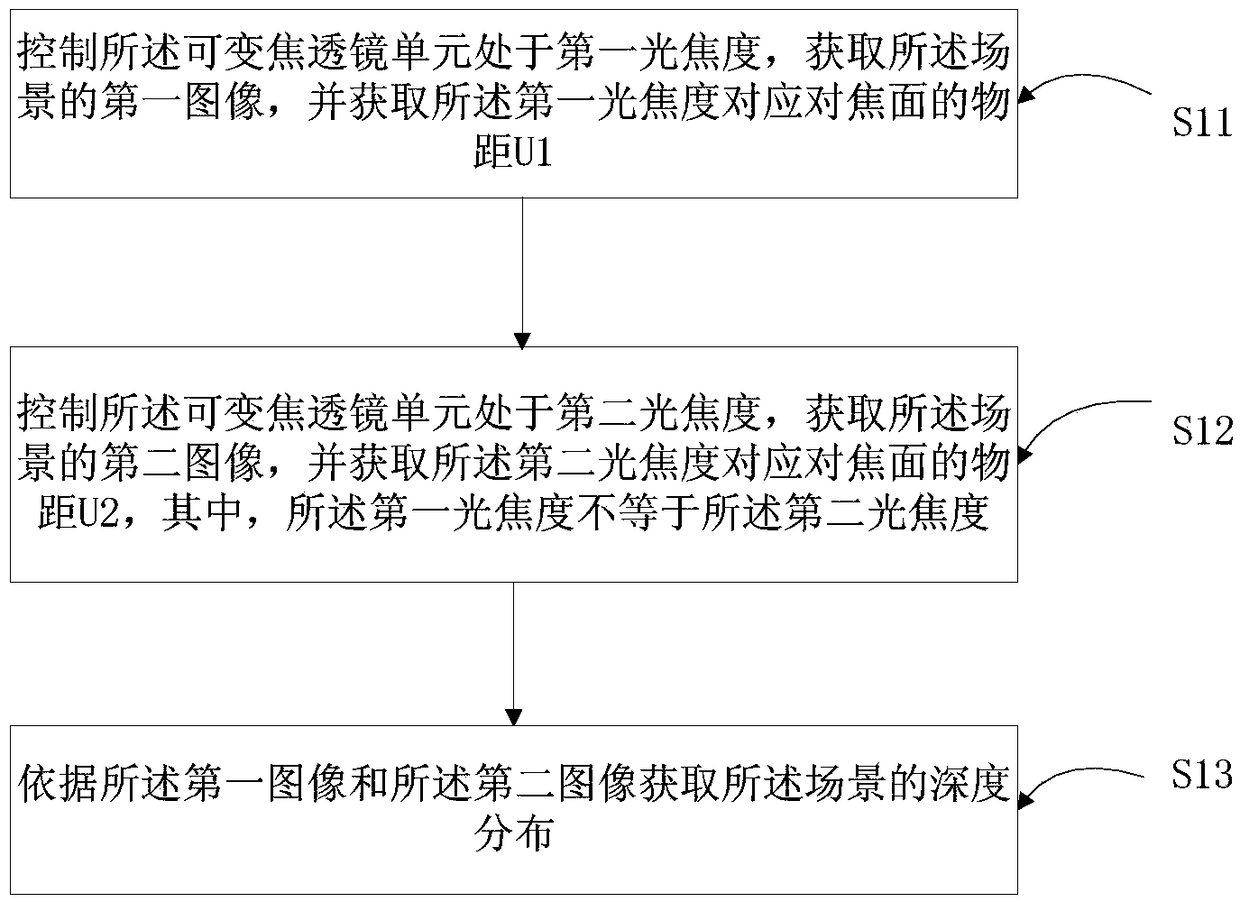
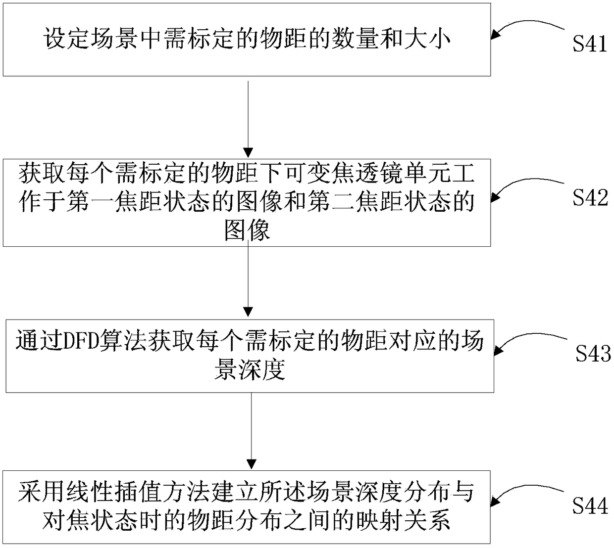
[0071] See Figure 1 to Figure 5 , figure 1 It is a flow chart of the autofocus method according to Embodiment 1 of the present invention, figure 2 for figure 1 An optional detailed flowchart of an embodiment of step S1, image 3 for figure 1 An optional detailed flowchart of another embodiment of step S1, Figure 4 for figure 1 An optional refinement flow chart of step S5 in, Figure 5 yes Figure 4 An optional detailed flow chart of step S51. Such as Figures 1 to 5 As shown, the present invention provides an autofocus method, and the autofocus method includes the following steps:

[0072] S1 obtains the depth distribution of a scene through a variable focus lens unit;

[0073] S2 acquires the depth value of the region of interest of the scene;

[0074] S3 According to the mapping relationship between the depth distribution and the object distance distribution of the scene, obtain the object distance value corresponding to the depth value of the region of interes...

Embodiment approach 2

[0112] See Figure 6 to Figure 10 , Figure 6 is a schematic structural diagram of an autofocus device according to an embodiment of the present invention, Figure 7 yes Figure 6 A schematic structural diagram of an embodiment of the medium-depth distribution acquisition unit, Figure 8 yes Figure 6 A schematic structural diagram of another embodiment of the mid-depth distribution acquisition unit, Figure 9 for Figure 6 Schematic diagram of the structure of the drive unit, Figure 10 for Figure 9 Schematic diagram of the structure of the mapping relationship establishment module. Such as Figure 6 to Figure 10 As shown, the present invention also provides an auto-focus device, and the auto-focus device includes:

[0113] A depth distribution acquisition unit 1, which acquires a depth distribution of a scene through a zoom lens unit;

[0114] The region of interest depth value acquisition unit 2 acquires the depth value of the region of interest of the scene;

...

Embodiment approach 3

[0140] See Figure 11 , Figure 11 It is a schematic structural diagram of an autofocus device according to another embodiment of the present invention. Such as Figure 11 As shown, the present invention also provides an autofocus device, including: a variable focus lens unit 110, an image sensor 130, a processor 100, and a memory 120, and the processor 100 controls the variable focus lens unit 110, the image sensor 130 and memory 120 work, the memory 120 is used to store computer-executed instructions, and the processor 100 reads the computer-executed instructions stored in the memory for controlling the variable focus lens unit 110 and the image sensor 130, configured to execute the autofocus method described in Embodiment 1, where the autofocus method includes the following steps:

[0141] S1 obtains the depth distribution of a scene through a variable focus lens unit;

[0142] S2 acquires the depth value of the region of interest of the scene;

[0143] S3 According to...


PUM


Abstract

The invention discloses an automatic focusing method, equipment and imaging device. The autofocus method includes: S1 obtaining the depth distribution of a scene through a variable focus lens unit; S2 obtaining the depth value of the region of interest of the scene; S3 according to the mapping relationship between the depth distribution and the object distance distribution of the scene, Obtain the object distance value corresponding to the depth value of the region of interest; S4 obtain the focal power value of the variable focus lens unit according to the Gaussian imaging formula; The mapping relationship between them is applied, and the driving voltage corresponding to the optical power value is applied to drive the variable focus lens unit. The present invention obtains the depth distribution of the scene through the variable focus lens unit, not only realizes rapid autofocus on the region of interest in the scene, but also obtains the depth map of the scene, providing more possibilities and convenience for image processing such as rendering or matting, Good user experience.

Description

technical field [0001] The present invention relates to the technical field of liquid crystal lenses, in particular to an autofocus method, autofocus equipment, and an imaging device based on the autofocus equipment. Background technique [0002] Because the liquid crystal lens and its array have the advantages of small size, light weight, low power consumption, etc., the feature of realizing adjustable focal length without mechanical parts shows a unique advantage. After several years of development, liquid crystal lenses and their arrays have great potential application value in various fields such as optical communication devices, optical fiber switches, light deflection devices, 3D displays, integrated image systems, and image processing. Imaging devices with liquid crystal lenses and arrays thereof have many important roles in national defense, scientific research, medical treatment and daily life. [0003] At present, the focus of camera equipment is mainly realized b...

Claims


Application Information

Patent Timeline
Patent Type & Authority Patents(China)
IPC IPC(8): G03B13/36H04N5/232G02B7/28
CPCG02B7/282G03B13/36H04N23/67
Inventor 李其昌
Owner 成都微晶景泰科技有限公司
Why Eureka
Try Eureka