Resonance elimination apparatus and method of ferromagnetic resonance

A ferromagnetic resonance and harmonic elimination technology, which is applied in circuit devices, emergency protection circuit devices, AC network circuits, etc. The effect of fast elimination of magnetic resonance, elimination of ferromagnetic resonance and improvement of harmonic elimination efficiency

Inactive Publication Date: 2016-12-14
YUNNAN POWER GRID CO LTD ELECTRIC POWER RES INST
View PDF5 Cites 17 Cited by
  • Summary
  • Abstract
  • Description
  • Claims
  • Application Information

AI Technical Summary

Problems solved by technology

[0004] However, the method of installing a resonance eliminator at the primary center point of the electromagnetic voltage transformer can prevent the ferromagnetic resonance between the three-phase voltage and the ground that is easily generated in the system, but for the power frequency resonance caused by disconnection The effect is poor, and it is easy to cause the voltage increase of the neutral point of the electromagnetic voltage transformer, the insulation breakdown of the end of the electromagnetic voltage transformer and other undesirable phenomena, causing the resonance eliminator to lose its function; adding a damping resistor will cause heat due to the damping resistor Affects the effect of ha

Method used


Image

  • Resonance elimination apparatus and method of ferromagnetic resonance
  • Resonance elimination apparatus and method of ferromagnetic resonance
  • Resonance elimination apparatus and method of ferromagnetic resonance

Examples


Embodiment Construction

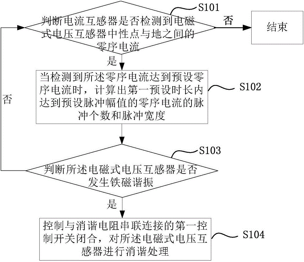
[0053] Reference will now be made in detail to the exemplary embodiments, examples of which are illustrated in the accompanying drawings. When the following description refers to the accompanying drawings, the same numerals in different drawings refer to the same or similar elements unless otherwise indicated. The implementations described in the following exemplary examples do not represent all implementations consistent with the present invention. Rather, they are merely examples of apparatuses and methods consistent with aspects of the invention as recited in the appended claims.

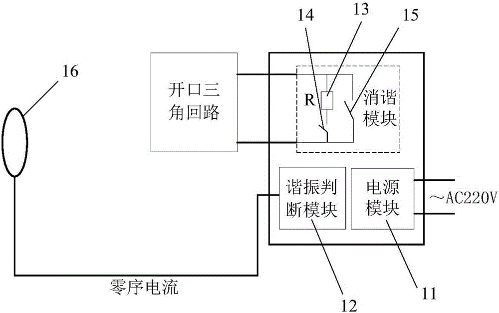
[0054] figure 1 It is a structural schematic diagram of a ferromagnetic resonance resonance elimination device according to an exemplary embodiment. As shown in 1, the device may include a power supply module 11, a resonance judgment module 12, a resonance elimination module and a current transformer 16 (CT, Current Transformer).

[0055] In the disclosed embodiment of the present invention, t...


PUM

PropertyMeasurementUnit
Resistanceaaaaaaaaaa

Abstract

The present invention relates to a resonance elimination apparatus and method of ferromagnetic resonance, wherein the apparatus is electrically connected to an electromagnetic voltage transformer in a power distribution network, and comprises: a power source module, a resonance judging module, a resonance elimination module, and a current transformer, wherein the power source module is electrically connected to the resonance judging module and the resonance elimination module; the current transformer is electrically connected to a connecting wire between a neutral point of the electromagnetic voltage transformer and the earth, and the current transformer is electrically connected to the resonance judging module; the resonance elimination module comprises a resonance elimination resistor and a first control switch, both ends of the resonance elimination resistor are connected to both ends of an open triangular loop of the electromagnetic voltage transformer in series, the first control switch is connected between the resonance elimination resistor and the open triangular loop in series; and the resonance judging module is electrically connected to the first control switch. The apparatus provided in this embodiment can accurately and fast eliminate ferromagnetic resonance and improve resonance elimination efficiency of ferromagnetic resonance.

Description

technical field [0001] The invention relates to the technical field of power system safety prevention and control, in particular to a ferromagnetic resonance resonance elimination device and method. Background technique [0002] In the distribution network below 66kV and below 66kV, a non-effective grounding system is usually adopted in which the neutral point of the system is not grounded and the neutral point is grounded through a small resistance or an arc suppression coil. The system bus is connected with an electromagnetic voltage for monitoring insulation to ground. Transformer (Potential Transformer, PT). Transient impacts caused by lightning strikes on the line, single-phase grounding, combined-air bus operation, drastic load changes, and secondary voltage-load switching may excite ferromagnetic resonance between the excitation reactance of the electromagnetic voltage transformer and the ground capacitance of the system . In recent years, frequent damage to electro...

Claims


Application Information

Patent Timeline
IPC IPC(8): H02H7/05H02J3/00
CPCH02H7/05H02J3/00H02J3/002
Inventor 刘红文王科
Owner YUNNAN POWER GRID CO LTD ELECTRIC POWER RES INST
Why Eureka
Try Eureka