
Compressor assembly and assembly method therefor

A technology for compressors and components, applied in the field of compressor components, can solve the problems of increasing the risk of damage to the evaporating plate and the like

Active Publication Date: 2019-03-26
BSH BOSCH & SIEMENS HAUSGERAETE GMBH
View PDF5 Cites 0 Cited by
  • Summary
  • Abstract
  • Description
  • Claims
  • Application Information

AI Technical Summary

Problems solved by technology

The greater this overlap, the more strongly the blocking hook has to be bent when pushed through the passage of the clip, so that the risk of damage to the evaporator tray also increases

Method used


Image

  • Compressor assembly and assembly method therefor
  • Compressor assembly and assembly method therefor
  • Compressor assembly and assembly method therefor

Examples


Embodiment Construction

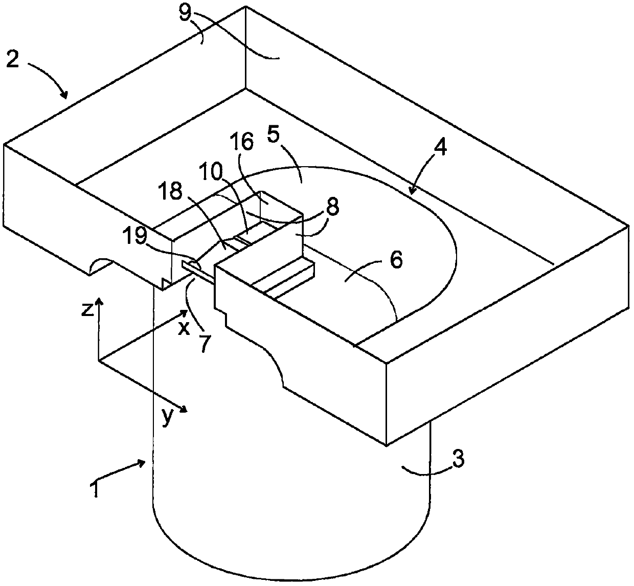
[0033] figure 1 The assembly according to the invention with a housing 1 and an evaporator plate 2 in which a compressor is installed is shown in a strongly schematic perspective view. The casing 1 basically has the configuration of a compact cylinder, wherein the casing 1 consists of figure 1 The transition from the visible outer surface 3 to the upper face of the housing, which is covered by the evaporator tray 2 in the figure, is rounded. In this case, the evaporator tray 2 essentially has the shape of a flat, upwardly open cuboid, on the bottom of which a bead 4 is formed. This bulge 4 comprises a semi-dome-shaped section 5 which rests tightly on the upper side of the casing 1 in order to achieve an efficient heat transfer from the compressor to the evaporator tray 2 and which The bulge comprises a section 6 terminating flush with the semi-dome-shaped section 5, the cross-section of which section 6 is constant in the direction indicated by X in the figure, and the upper ...


PUM


Abstract

A compressor module for a domestic refrigeration appliance comprises a compressor and an evaporation tray (2). A clip (10) is fitted to a capsule (1) of the compressor in order to define a passage (14) between the capsule (1) and the clip (10). A latching channel (7) is formed in the evaporation tray (2). The compressor (1) and the evaporation tray (2) are displaced in the longitudinal direction (x) of the latching channel (7) from a free position, in which the clip (10) engages in the latching channel (7) and the passage (14) is free of parts of the evaporation tray (2), into a latching position, in which an insertion finger (17) of the evaporation tray (2) is pushed into the passage (14) from a front side (23) of the clip (10) and a contact face (20) of an elastically deflectable finger (18) of the evaporation tray (2) acts on a rear side (21) of the clip (10), characterized in that the elastic finger (18) extends beyond the rear side (21) of the clip (10) as far as a base (19) which is stationary on the evaporation tray (2) and which is further away from the rear side (21) of the clip (10) than the contact face (20).

Description

technical field [0001] The invention relates to a compressor assembly with a compressor housing and an evaporator disk for a domestic refrigeration appliance and a method for its assembly. Background technique [0002] A compressor installed in a compressor housing heats the housing to a temperature between 40° and 60° C. during operation. This heat is used in a conventional manner to cause the dew to evaporate in an evaporation pan mounted on the compressor housing. A good heat transfer between the compressor housing and the evaporator disk is necessary for this. Therefore, the contours of the compressor housing and the evaporator must be precisely adapted to each other, and the evaporator must be securely fastened to the compressor housing. [0003] The usual principle for fastening the evaporator plate to the compressor housing is snap-in by means of a snap-fit ​​connection. Such a snap connection conventionally consists of a clip welded on the upper side of the compre...

Claims


Application Information

Patent Timeline
Patent Type & Authority Patents(China)
IPC IPC(8): F25D21/14
CPCF25D21/14F25D2321/1411F25D2321/143F25D2321/1442
Inventor B·格拉泽A·克默尔P·顺德纳S·施泰宁格M·韦劳赫
Owner BSH BOSCH & SIEMENS HAUSGERAETE GMBH
Learn More