Reciprocating type punching device

A punching device, reciprocating technology, applied in the direction of punching machines, presses, manufacturing tools, etc., can solve the problems of increased grinding time, reduced efficiency, reduced hydraulic oil impact force, etc., to improve punching efficiency and reduce Grinding time, effect of reducing punching time

Active Publication Date: 2016-12-21
重庆新钰立金属科技有限公司
View PDF7 Cites 3 Cited by
  • Summary
  • Abstract
  • Description
  • Claims
  • Application Information

AI Technical Summary

Problems solved by technology

[0004] The problems of the above punching machine: 1. The hydraulic cylinder generally needs to be controlled by an oil pump. After the oil pump pressurizes the oil, the oil with a certain pressure will press the piston to move. It takes a certain time to provide the punch power in the whole process, and the efficiency will decrease. 2. The process of the hydraulic cylinder controlling the punch and the movement of the hydraulic oil will greatly reduce the instantaneous impact force of the hydraulic oil, which cannot guarantee the instantaneous punching force of the punch, resulting in more damage to the wall of the punched hole. Burrs, increasing grinding time

Method used


Image

  • Reciprocating type punching device

Examples


Embodiment Construction

[0015] The present invention will be described in further detail below by means of specific embodiments:

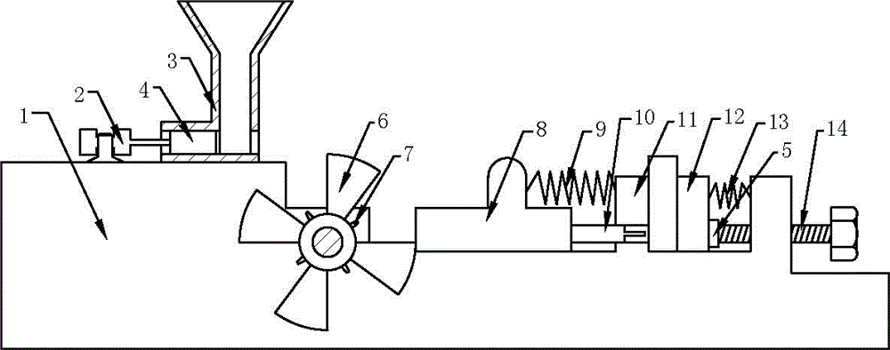
[0016] The reference signs in the drawings of the description include: frame 1, cylinder 2, hopper 3, push block 4, backing plate 5, partition plate 6, flame nozzle 7, push plate 8, compression spring 9, punch 10, fixed Clamping plate 11, punching seat 12, extension spring 13, screw rod 14.

[0017] Example basic reference figure 1 Shown: a reciprocating punching device, including a frame 1, a punch 10 and a punching seat 12 sequentially arranged on the frame 1, and a fixed frame 1 is fixed on the frame 1 between the punch 10 and the punching seat 12. The splint 11, the fixed splint 11 is integrally formed with the frame 1, the punch 10 passes through the fixed splint 11 and is slidably connected with the fixed splint 11, the compression spring 9 is connected between the punch 10 and the fixed splint 11, and the punching seat 12 is slidably connected On the frame 1, a q...


PUM


Abstract

The invention discloses a reciprocating type punching device which comprises a rack, and a punch head and a punching seat that are arranged on the rack sequentially; a first spring is connected between the punch head and the rack; and the punching seat is slidingly connected with the rack. The reciprocating type punching device further comprises an explosive rotary plate and an intermittent pushing mechanism for pushing an explosive into the explosive rotary plate intermittently; the intermittent pushing mechanism is arranged on one side, far from the punching seat, of the punch head; the explosive rotary plate is arranged between the intermittent pushing mechanism and the punch head, and is rotationally connected with the rack; partition plates are uniformly distributed in the circumferential direction of the explosive rotary plate; a containing cavity containing the explosive is formed between every two partition plates; a flaming mouth is formed in each containing cavity; and a pushing plate is fixedly connected with one end, close to the explosive rotary plate, of the punch head, and is abutted against one partition plate. Compared with the prior art, the explosive reacts more quickly, an instant impact force of the explosive is greater, the punching time can be reduced and the punching efficiency can be improved; and a punching force of the punch head can be ensured, so that when the punch head punches a workpiece, fewer burrs are generated around the hole wall, and the polishing time is reduced.

Description

technical field [0001] The invention relates to a feeding device, in particular to a reciprocating punching device. Background technique [0002] Punching refers to punching various graphics on steel plates, leather, cloth, wood and other materials to meet different needs. When making some sheet metal parts, pipe fittings or hardware parts, it is often necessary to open holes on the workpiece to meet production need. [0003] The existing punching machine includes a hydraulic cylinder, a punch and a punching seat. The punching seat is fixed below the punch, and the hydraulic cylinder is connected to the top of the punch. The punch moves down and punches the workpiece on the punching seat out of the hole, completing the basic punching operation. [0004] The problems of the above punching machine: 1. The hydraulic cylinder generally needs to be controlled by an oil pump. After the oil pump pressurizes the oil, the oil with a certain pressure will press the piston to move. I...

Claims


Application Information

Patent Timeline
IPC IPC(8): B21D28/24B30B1/00
CPCB21D28/24B30B1/001
Inventor 陈建国
Owner 重庆新钰立金属科技有限公司
Why Eureka
Try Eureka