Punching device

A punching device and punching technology, applied in the orientation of circuit board tools, metal processing, electrical components, etc., can solve the problems of long punching time and low punching efficiency, improve punching efficiency, reduce waiting time, The effect of shortening the punching time

Inactive Publication Date: 2021-12-21
KINWONG ELECTRONIC TECH (ZHUHAI) CO LTD
View PDF5 Cites 0 Cited by
  • Summary
  • Abstract
  • Description
  • Claims
  • Application Information

AI Technical Summary

Problems solved by technology

[0004] After receiving the core board, the traditional punching device grabs the target on the core board through the punching alignment camera, and adjusts the position of the core board so that the target is aligned with the theoretical position to complete the precise alignment, and finally punches down After finishing the punching, because the target on the core plate is often far from the theoretical position, the position of the core plate must be adjusted in a large range before each punching, resulting in longer punching time and lower punching efficiency

Method used


Image

  • Punching device
  • Punching device
  • Punching device

Examples


Embodiment Construction

[0039] In order to make the object, technical solution and advantages of the present invention clearer, the present invention will be further described in detail below in conjunction with the accompanying drawings, that is, embodiments. It should be understood that the specific embodiments described here are only used to explain the present invention, not to limit the present invention.

[0040] It should be noted that when an element is referred to as being “fixed” or “disposed on” another element, it may be directly on the other element or be indirectly on the other element. When an element is referred to as being "connected to" another element, it can be directly connected to the other element or indirectly connected to the other element.

[0041] In addition, the terms "first" and "second" are used for descriptive purposes only, and cannot be interpreted as indicating or implying relative importance or implicitly specifying the quantity of indicated technical features. Th...


PUM


Abstract

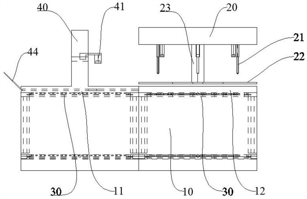
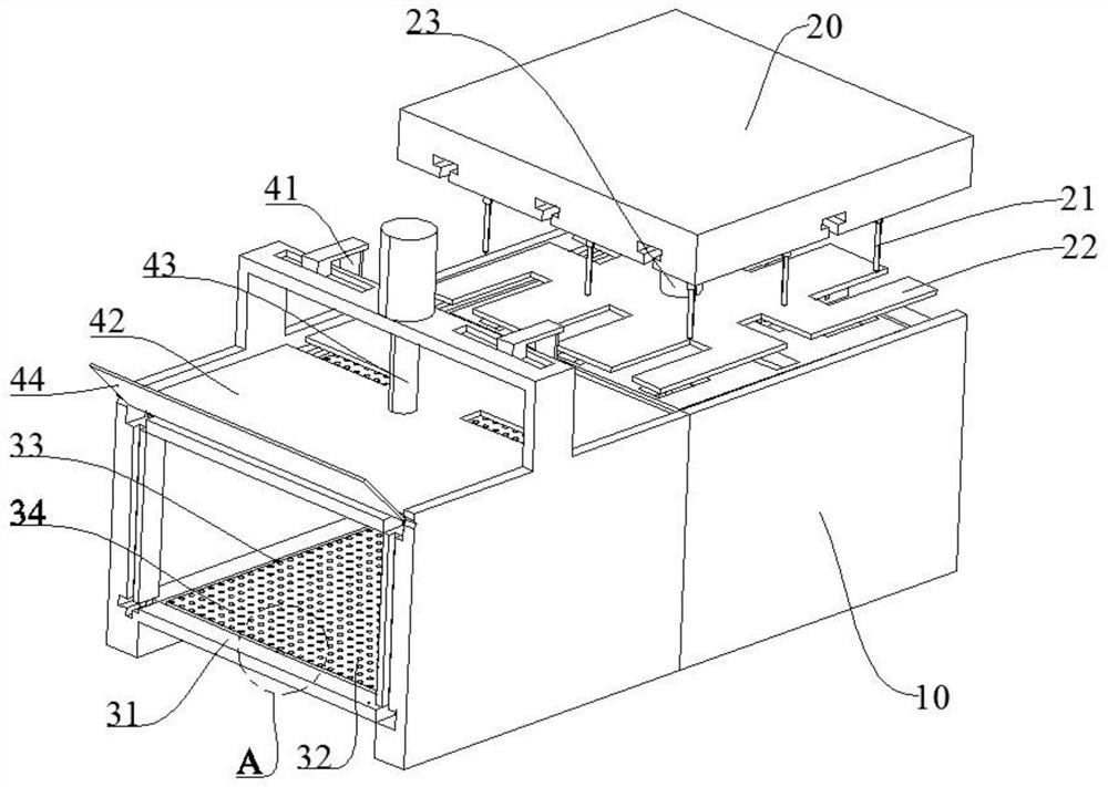
The invention relates to the technical field of circuit board manufacturing, and provides a punching device. The punching device comprises a rack, a punching mechanism and at least two workbenches, wherein the rack is provided with a feeding position and a punching position; the punching mechanism is arranged above the punching position; the at least two workbenches are used for bearing core boards; and the at least two workbenches can circularly move between the feeding position and the punching position, so that the punching mechanism is used for punching the core boards on the workbenches moved to the punching position. According to the punching device, after the core boards are positioned to one of the workbenches, the workbench can be moved to the punching position firstly, then the core boards on the workbenches are directly punched through the punching mechanism, the positions of the core boards do not need to be adjusted before punching, the punching precision is high, the punching time of the punching device is shortened, the waiting time is shortened, and the punching efficiency is improved.

Description

technical field [0001] The invention relates to the technical field of circuit board manufacturing, in particular to a punching device. Background technique [0002] At present, in the production of circuit boards, core boards are often used to process multi-layer circuit boards. According to whether the thickness of the copper layers on both sides is equal, the core boards can be divided into symmetrical core boards (equal copper thickness on both sides) and asymmetrical core boards (both sides have equal copper thickness). The copper thickness varies), and the asymmetric core board is also called the yin and yang copper core board. [0003] OPE (Optical Punch Equipment, optical punching equipment) punching is an indispensable part of the multilayer circuit board processing process. Before multiple core boards are pressed into a multilayer circuit board, in order to prevent the If there are quality problems such as layer deviation and sliding board after the boards are sta...

Claims


Application Information

Patent Timeline
Patent Type & Authority Applications(China)
IPC IPC(8): B26F1/24B26D7/01B26D5/00B26D7/06H05K3/00
CPCB26F1/24B26D7/01B26D5/00B26D7/0625H05K3/0008H05K3/005
Inventor 马万年胡新星张佳胡绪兵肖永龙罗耀东
Owner KINWONG ELECTRONIC TECH (ZHUHAI) CO LTD
Why Eureka
Try Eureka