
Drilling device for auto parts

A technology for auto parts and punching devices, applied in positioning devices, metal processing machinery parts, boring/drilling and other directions, can solve the problem of inability to ensure the same force applied by workers, low punching efficiency, and large difference in depth, etc. problems, to achieve the effect of shortening the punching time, reducing the time of idling operation, and improving efficiency

Active Publication Date: 2020-04-28
宁波隆锐机械制造有限公司
View PDF10 Cites 0 Cited by
  • Summary
  • Abstract
  • Description
  • Claims
  • Application Information

AI Technical Summary

Problems solved by technology

[0004] Although the above-mentioned patent solution solves the deficiencies in the traditional punching method to a certain extent, there are still some points to be improved in this solution: when the punching machine is punched, the worker needs to hold the handle to operate. On the one hand, punching The efficiency of the hole is still not high. On the other hand, although there is a resistance block to prevent the hole from being punched through too much force, it still cannot guarantee that the worker applies the same force every time, so it is easy As a result, the depth of the holes after processing the same batch of auto parts is quite different, resulting in a decline in the pass rate

Method used


Image

  • Drilling device for auto parts

Examples


Embodiment Construction

[0021] The present invention will be further described in detail below through specific implementations:

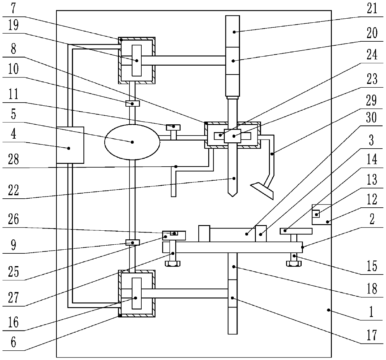
[0022] The reference signs in the drawings of the specification include: frame 1, workbench 2, fasteners 3, air supply box 4, air bag 5, first air chamber 6, second air chamber 7, third air chamber 8, first One-way valve 9, second one-way valve 10, valve 11, third slider 12, second touch switch 13, second slider 14, second screw 15, first turbine 16, first gear 17, first A rack 18, a second turbine 19, a second gear 20, a second rack 21, a perforated column 22, a spline sleeve 23, a third turbine 24, a first slider 25, a first touch switch 26, a first A screw 27, a support rod 28, an exhaust pipe 29, and parts 30.

[0023] This embodiment is basically as attached figure 1 Shown:

[0024] The punching device for automobile parts includes a frame 1, a workbench 2 is slidably connected to the frame 1, and a fastener 3 for clamping parts 30 is provided on the workbench 2; the fra...


PUM


Abstract

The invention relates to the technical field of automobile part processing and discloses a perforating device for automobile parts. The perforating device for automobile parts comprises a rack, wherein a worktable is slidably connected to the rack and an air supply box is fixedly connected to the rack; a first air chamber and a second air chamber communicate to the air supply box; a first worm wheel is rotatably connected to the first air chamber; a first gear is coaxially connected to the first worm wheel; a first rack is engaged to the first gear; a second worm wheel is rotatably connected in the second air chamber; a second gear is coaxially connected to the second worm wheel; a second rack is engaged to the second gear; a perforating pile is rotatably connected to the second rack; a spline sleeve sleeves the perforating pile; a third air chamber communicating to the first and second air chambers is fixedly connected to the rack; a third worm wheel is connected to the spline sleevein a sleeving manner; an adjusting mechanism is arranged on the worktable; a first touch switch for closing the air supply box is mounted on the adjusting mechanism; and a supporting rod leaning against the first touch switch is arranged on the third air chamber. The perforating device for automobile parts provided by the invention can adjust the perforating depth and improves the perforating efficiency.

Description

Technical field [0001] The invention relates to the technical field of automobile parts processing, in particular to a punching device for automobile parts. Background technique [0002] During the processing of auto parts, in order to facilitate the installation of auto parts, the auto parts are usually punched. Traditional drilling methods use manual hand-held drilling machines for drilling. During the drilling process, the force cannot be kept the same each time, which easily leads to inconsistent depths of the holes on the auto parts after the same batch of drilling, resulting in automobile zero The parts have different specifications, which reduces the qualified rate of processing, and manual drilling is labor-intensive and low in efficiency, which is not suitable for mass production. [0003] In order to solve the above-mentioned problems, the Chinese patent (CN104174758B) discloses a hole pressing machine for auto parts. The hole pressing machine includes a trapezoidal supp...

Claims


Application Information

Patent Timeline
Patent Type & Authority Patents(China)
IPC IPC(8): B23B41/00B23Q3/06B23Q11/10B23Q11/00
CPCB23B41/00B23Q3/06B23Q11/005B23Q11/10
Inventor 卢文斌
Owner 宁波隆锐机械制造有限公司
Learn More