
A device for punching holes in fixed-cut fabrics in a garment factory

A punching device, a technology for a garment factory, applied in metal processing and other directions, can solve the problems of cumbersome operation process, labor-intensive, low work efficiency, etc., and achieve the effects of simple operation, improved work efficiency, and manpower saving

Active Publication Date: 2022-05-06
山东靓华制衣有限公司
View PDF0 Cites 0 Cited by
  • Summary
  • Abstract
  • Description
  • Claims
  • Application Information

AI Technical Summary

Problems solved by technology

[0006] In order to overcome the disadvantages that the operation process of the above method is cumbersome, the operation is relatively labor-intensive, and only one hole can be punched at a time during the operation, and the work efficiency is low, the technical problem to be solved by the invention is to provide an operation A simple, manpower-saving, and efficient garment factory fixed-cut fabric punching device

Method used


Image

  • A device for punching holes in fixed-cut fabrics in a garment factory
  • A device for punching holes in fixed-cut fabrics in a garment factory
  • A device for punching holes in fixed-cut fabrics in a garment factory

Examples


Embodiment 1

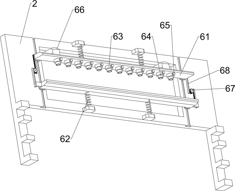
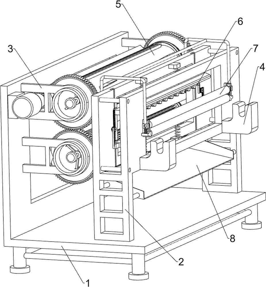
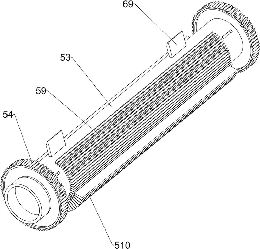
[0028] A kind of clothing factory fixed cutting cloth punching device, such as Figure 1-7 As shown, it includes a frame 1, a support base 2, a mounting frame 3 and a support frame 4. The support base 2 is connected to the top right side of the frame 1, and two sets of mounting frames 3 are connected to the left side of the frame 1. Each set of mounting frames 3 is two settings, the two installation frames 3 of each group are respectively connected to the front and rear sides of the frame 1, and the support frame 4 is connected to the front and rear sides of the right side of the support seat 2, and also includes an adjustable feeding mechanism 5 and a punching machine. The hole device 6 is provided with an adjustable feeding mechanism 5 between the mounting frame 3 and the frame 1 , and a punching device 6 is provided between the adjustable feeding mechanism 5 and the support seat 2 .

[0029] The adjustable feeding mechanism 5 includes a reduction motor 51, a drive gear 52, ...

Embodiment 2

[0033] On the basis of Example 1, such as Figure 8 As shown, the fixed assembly 7 is also included, and the fixed assembly 7 includes a guide frame 71, a lower fixed roller 72, a slider 73, a tension spring 74, an upper fixed roller 75 and a handle frame 76, and the left and right sides of the support seat 2 are connected with a Group guide frame 71, every group guide frame 71 is two settings, two guide frames 71 of every group are respectively connected on the front and rear sides of support seat 2, and all rotatably connected with lower fixed roller between the guide frame 71 bottoms of each group 72, on the guide frame 71, slide type is connected with slide block 73, is connected with extension spring 74 between slide block 73 and guide frame 71, is all rotatably connected with upper fixed roller 75 between the slide block 73 of every group of guide frame 71, The upper fixed roller 75 cooperates with the lower fixed roller 72 , and a handle frame 76 is connected between th...


PUM


Abstract

The invention relates to a punching device, in particular to a punching device for fixedly cut cloth in a garment factory. The technical problem to be solved by the present invention is a garment factory fixed cutting cloth punching device which is easy to operate, can save manpower and improve work efficiency. In order to solve the above-mentioned technical problems, the present invention provides such a device for punching holes in fixedly cut fabrics in a garment factory, which includes: a frame with a support base connected to one side of its top; The racks are connected to the other side of the rack, and each set of mounting racks has two settings, and the two mounting racks of each group are respectively connected to both sides of the rack; Both sides of the support seat. The invention punches the cloth through the cooperative operation of the adjustable feeding mechanism and the punching device, thereby achieving the effect of punching the cloth.

Description

technical field [0001] The invention relates to a punching device, in particular to a punching device for fixedly cut cloth in a garment factory. Background technique [0002] When making clothes, it is usually necessary to use cloth, which is a kind of material commonly used in decorative materials. The cloth is divided into chemical fiber carpet, non-woven wall covering, linen cloth, nylon cloth, colored tape, flannel and other cloth. Cloth can play an important role in the display of decoration, and it is usually the main force that cannot be ignored in the entire sales space. When making some items, the cloth needs to be punched. [0003] At present, the method of punching the cloth is usually to manually clamp the cloth first, and then the user holds the punching device to punch the cloth. The medium can only punch one hole at a time, and the work efficiency is low. [0004] Therefore, it is necessary to develop a garment factory fixed cutting cloth punching device th...

Claims


Application Information

Patent Timeline
Patent Type & Authority Patents(China)
IPC IPC(8): B26F1/16B26D7/06B26D7/26B26D7/02
CPCB26F1/16B26D7/06B26D7/2614B26D7/025
Inventor 闵芳
Owner 山东靓华制衣有限公司
Learn More