New-generation information technology photoelectric module shell punching device

A technology of photoelectric modules and information technology, applied in the direction of feeding devices, storage devices, positioning devices, etc., can solve the problems of automatic punching, automatic delivery of module shells, and automatic clamping of module shells, etc., to achieve The effect of the sliding collection effect

Pending Publication Date: 2021-12-28
张治周
View PDF6 Cites 0 Cited by
  • Summary
  • Abstract
  • Description
  • Claims
  • Application Information

AI Technical Summary

Problems solved by technology

[0005] In order to overcome the shortcomings that the traditional shell punching device cannot realize automatic delivery of the module shell, automatic punching and automatic clamping of the module shell, the technical problem to be solved is: to provide a method for automatically transporting the module shell and automatically punching A new generation of information technology photoelectric module shell punching device with automatic clamping module shell

Method used


Image

  • New-generation information technology photoelectric module shell punching device
  • New-generation information technology photoelectric module shell punching device
  • New-generation information technology photoelectric module shell punching device

Examples


Embodiment 1

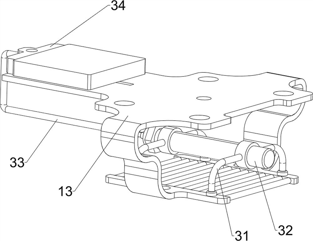
[0056] A new generation of information technology photoelectric module shell punching device, such as Figure 1-Figure 3 As shown, it includes a base 1, a pillar 11, a discharge box 12, a workbench 13, a slideway 14, a collection box 15, a punching mechanism 2 and a feeding mechanism 3, the base 1 is provided with a pillar 11, and the upper part of the pillar 11 is provided with Discharging box 12, pillar 11 front side is provided with workbench 13, and workbench 13 front side is provided with collection box 15, and collection box 15 rear side top is provided with slideway 14, and workbench 13 is provided with punching mechanism 2, and work The stage 13 is provided with a feeding mechanism 3 .

[0057] When people want to punch the module shell, this new generation of information technology photoelectric module shell punching device can be used. At first, the user puts the module shell into the discharge box 12, and the module shell is dropped by the discharge box Fall on the...

Embodiment 2

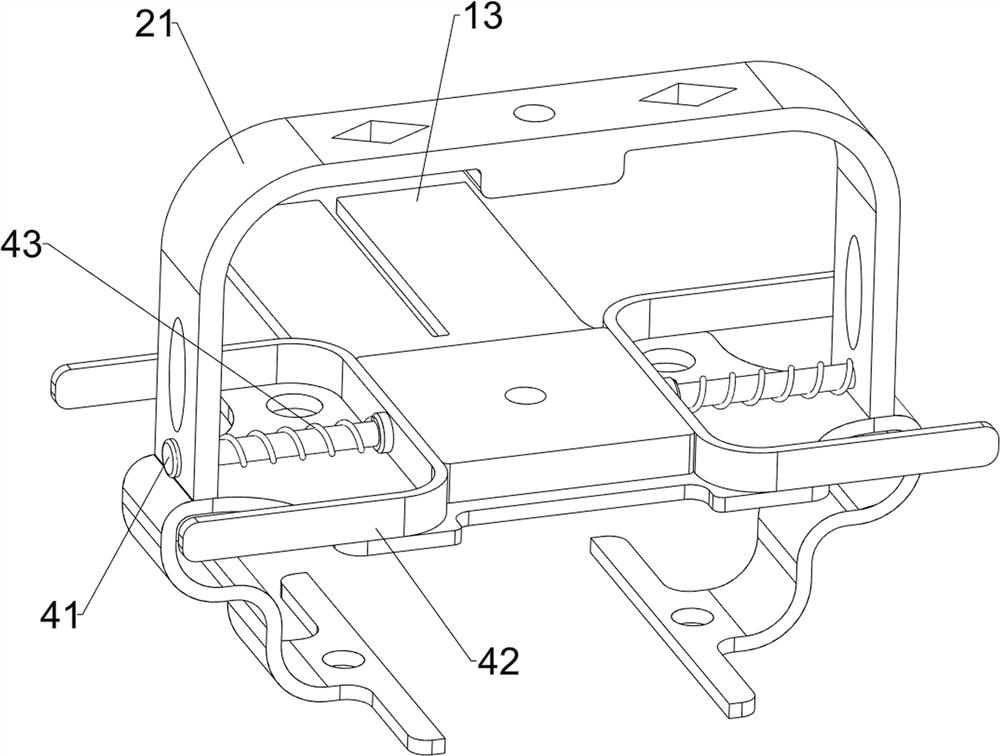
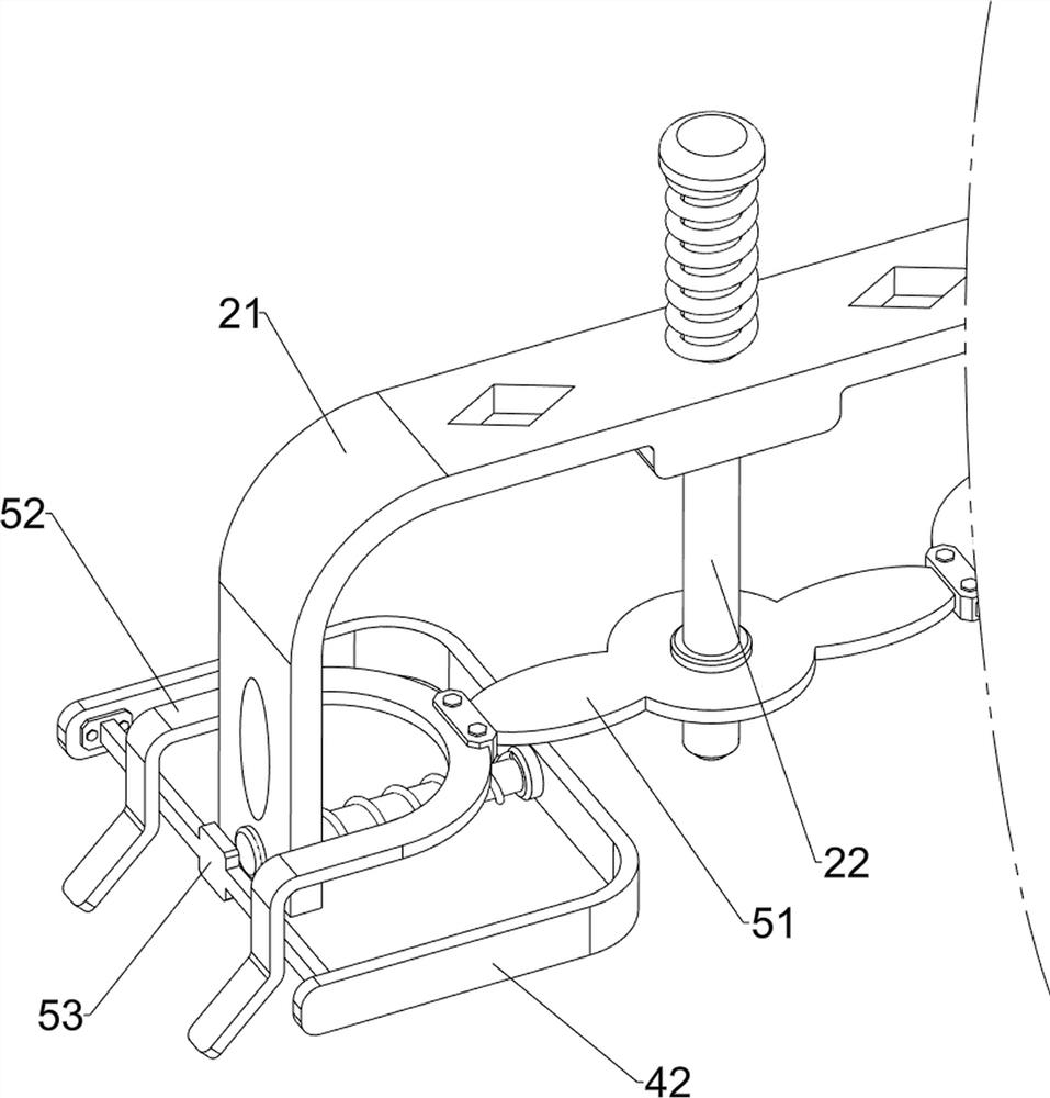
[0063] On the basis of Example 1, such as Figure 4-Figure 7 As shown, a clamping mechanism 4 is also included. The first bracket 21 is provided with a clamping mechanism 4. The clamping mechanism 4 includes a second sliding column 41, a clamp 42 and a second spring 43. The left and right sides of the first bracket 21 The even sliding type is provided with a second sliding post 41, two second sliding posts 41 are provided with clamps 42, two second sliding posts 41 are wound with a second spring 43, and the two ends of the second spring 43 are connected with the clamps respectively. 42 is connected with the first bracket 21.

[0064] When the module casing is located below the first sliding column 22, the user pushes the clamp 42 inwardly, the clamp 42 drives the second sliding column 41 to move inwardly, the second spring 43 is stretched, and after the clamp 42 contacts the module casing, the clamp 42 42 Clamp the module shell to achieve the effect of the clamp 42 clamping t...


PUM


Abstract

The invention relates to a shell punching device, in particular to a new-generation information technology photoelectric module shell punching device. The invention provides the new-generation information technology photoelectric module shell punching device which realizes automatic conveying of module shells, automatically punching and automatically clamping the module shells. The new-generation information technology photoelectric module shell punching device comprises a base, a material placement box, a workbench, a collecting box, a sliding way, a punching mechanism and a feeding mechanism; a supporting column is arranged on the base; the material placement box is arranged at the upper part of the supporting column; the workbench is arranged on the supporting column; the collecting box is arranged on the workbench; the sliding way is arranged at the upper part of the collecting box; the punching mechanism is arranged on the workbench; and the feeding mechanism is arranged on the workbench. According to the device, a first sliding column is pressed downwards, and a first spring is compressed, so that the first sliding column punches the module shells, and the effect that the first sliding column punches the module shells is achieved.

Description

technical field [0001] The invention relates to a shell punching device, in particular to a new generation information technology photoelectric module shell punching device. Background technique [0002] For the same type of communication facility signal transmitter, the ability to receive and transmit signals will be affected by factors such as terrain and height, and the function of the communication facility is too single. When the signal transmitter fails, it cannot be repaired in time. , the heat dissipation effect of the signal transmitter itself is not ideal, the signal transmitter is immovable, and the number is small, which will affect the ability of data transmission. [0003] Patent application CN206195757U, with a publication date of 20170524, discloses a signal transmitter for communication facilities, including a communication tower, a high light, a fixed bracket, a rotating rod, a motor, a slideway, a sealed box, a rotating shaft, a cooling plate and a ring si...

Claims


Application Information

Patent Timeline
Patent Type & Authority Applications(China)
IPC IPC(8): B21D28/34B21D43/00B21D43/02B21D43/22
CPCB21D28/34B21D43/003B21D43/027B21D43/22
Inventor 张治周
Owner 张治周
Why Eureka
Try Eureka