Eureka AIR delivers breakthrough ideas for toughest innovation challenges, trusted by R&D personnel around the world.

Ring shifting arranging, polishing and forming collecting equipment

A collection equipment and automatic arrangement technology, applied in grinding/polishing equipment, metal processing equipment, grinding machines, etc., can solve the problems of large manpower consumption, complex structure, low efficiency, etc., and achieve high-quality and high-efficiency grinding and arrangement The effect of high efficiency and simple structure

Inactive Publication Date: 2016-12-21
佛山市顺德区凯丰恒五金制品有限公司
View PDF6 Cites 0 Cited by
  • Summary
  • Abstract
  • Description
  • Claims
  • Application Information

AI Technical Summary

Problems solved by technology

[0004] One of the purposes of the present invention is to address the deficiencies of the prior art and overcome the need for large manpower to arrange the breaches of the piston rings in the prior art and then polish them and the poor stability and efficiency of the grinding equipment after the piston rings are broken. Low cost, complex structure, high failure rate and the problem that the polished piston ring cannot be shaped and collected

Method used


Image

  • Ring shifting arranging, polishing and forming collecting equipment
  • Ring shifting arranging, polishing and forming collecting equipment
  • Ring shifting arranging, polishing and forming collecting equipment

Examples


Embodiment

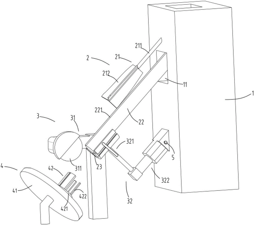
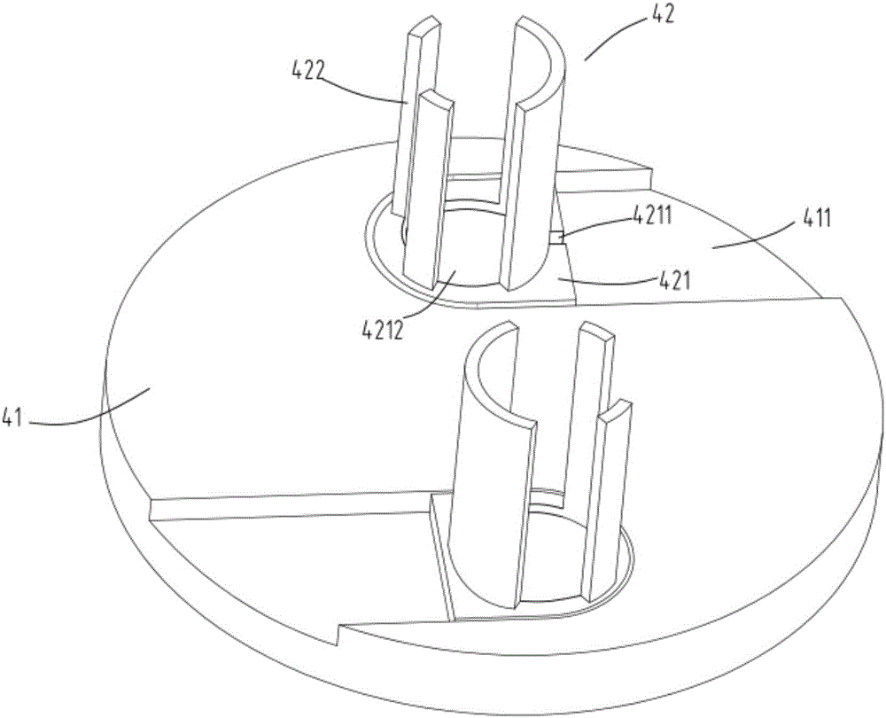
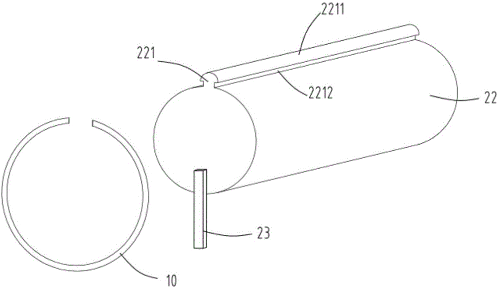
[0028] figure 1 It is a structural schematic diagram of a kind of ring toggle arrangement grinding and shaping collection equipment, figure 2 Schematic diagram of the structure of the stereotyped collection device, image 3 is a schematic diagram of the rod, Figure 4 A schematic diagram of the automatic arrangement device, Figure 5 A cross-sectional schematic diagram of the automatic arrangement device. Such as figure 1 , figure 2 , image 3 , Figure 4 and Figure 5 As shown in the figure, a ring toggle arrangement grinding and shaping collection equipment includes a splitting machine 1, an automatic alignment device 2, a polishing device 3 and a shaped collection device 4; the automatic alignment device 2 is arranged at the material outlet of the splitting machine 1 11 places, which are used to arrange the piston rings 10 that have been breached neatly in a line at the breach; Grinding; the sizing collection device 4 is arranged at the rear end of the grinding d...


PUM


Abstract

The invention relates to ring shifting arranging, polishing and forming collecting equipment. The equipment comprises a breaking machine, an automatic arranging device, a polishing device and a forming collecting device, wherein the automatic arranging device is arranged at a discharge hole of the breaking machine and used for trimly arranging piston rings after breaking at the breaking position in a straight line shape; the polishing device is arranged at the rear end of the automatic arranging device and used for polishing the breaking position of the trimly arranged piston rings; the forming collecting device is arranged at the rear end of the polishing device and used for collecting the polished piston rings; the automatic arranging device comprises a rotary material shifting brush arranged on the breaking machine, a material bar extending outwards from the discharge hole of the breaking machine and inclining downwards, and a material stop plate arranged at the tail end of the material bar. The equipment disclosed by the invention can overcome the problems of the prior art that a large quantity of manpower needs to be consumed to arrange and polish openings of the piston rings after the piston rings are broken, the polishing equipment is poor in stability, low in efficiency, complicated in structure and high in fault rate, and the polished piston ring cannot be formed and collected.

Description

technical field [0001] The invention relates to the technical field of piston ring production equipment, in particular to a ring dial arrangement grinding and shaping collection equipment. Background technique [0002] Piston rings are commonly used mechanical parts. During the production process of piston rings, the rings are usually broken on the breaking machine first, and then the workers take the broken piston rings to be polished, and some are manually polished one by one. The quality of the piston rings is good but the efficiency is low and the labor cost is high; some equipment that can realize automatic grinding generally needs to manually arrange the piston rings according to the breaks and then load and polish them. The workers need to stand aside and straighten the breaks The location and operation are more troublesome, and the grinding of the cracks of the piston rings is also done one by one by pushing the hydraulic cylinder. The piston rings are relatively sma...

Claims


Application Information

Patent Timeline
Patent Type & Authority Applications(China)
IPC IPC(8): B24B9/00B24B41/00B24B41/06B65G47/26B65G47/74
CPCB24B9/005B24B41/00B24B41/005B24B41/06B65G47/26B65G47/74
Inventor 丁震华
Owner 佛山市顺德区凯丰恒五金制品有限公司
Why Eureka
Eureka Blog
Learn More