
An ultrasonic welding device

A technology of ultrasonic welding and ultrasonic vibration, applied in the field of ultrasonic welding, can solve the problems of fragile workpiece damage, occupying a large space, reducing the rigidity of the tool, etc., and achieve the effect of improving the rigidity of the system and the compact structure.

Active Publication Date: 2018-09-14
SBT ULTRASONIC TECH CO LTD
View PDF6 Cites 0 Cited by
  • Summary
  • Abstract
  • Description
  • Claims
  • Application Information

AI Technical Summary

Problems solved by technology

[0004] At present, the vibration direction of most ultrasonic welding devices is the same as the working direction, and this method is easy to cause damage to fragile workpieces
The vibration direction perpendicular to the working direction will reduce the rigidity of the tool and cause defects in the welding point
In addition, during ultrasonic welding, one product usually corresponds to one type of bottom mold and a certain working stroke. The stroke of the current ultrasonic welding device is first moved to the required position and then fixed. It is impossible to accurately set the distance, and it is troublesome to replace the bottom mold. Take up a lot of space

Method used


Image

  • An ultrasonic welding device
  • An ultrasonic welding device
  • An ultrasonic welding device

Examples


Embodiment Construction

[0022] The ultrasonic welding device of the present invention is compact in structure, sufficiently rigid and easy to operate, and can realize ultrasonic welding of plastic parts. The specific structure is as follows:

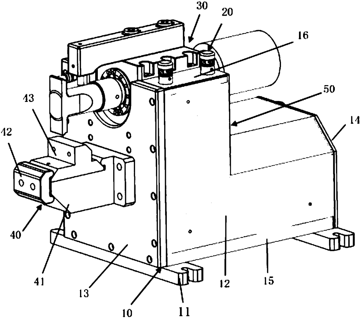
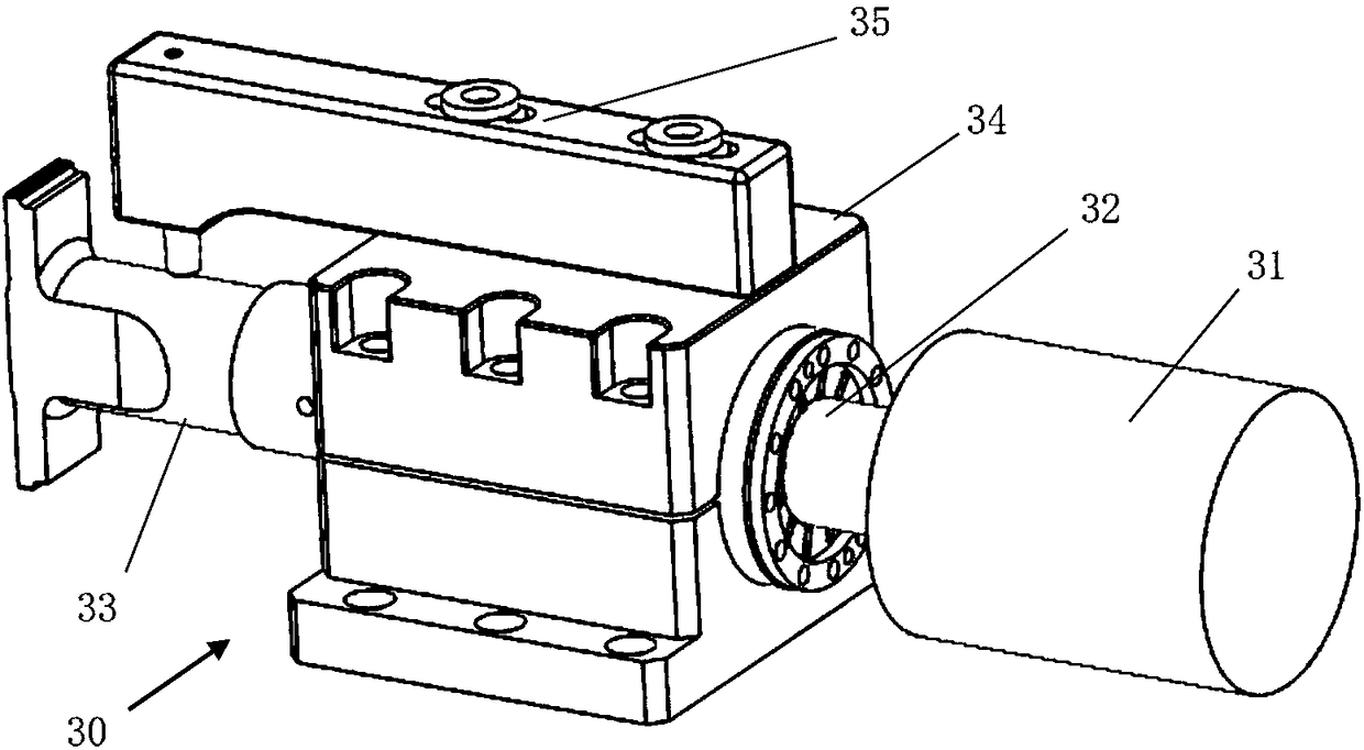
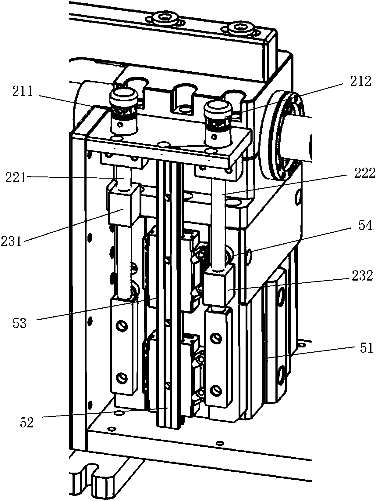
[0023] figure 1 It is a structural diagram of the ultrasonic welding device of the present invention, and the ultrasonic welding device includes a base 10 , a stroke adjustment system 20 , an ultrasonic vibration device 30 , a bottom mold part 40 and a power drive system 50 . The base 10 includes an anchor 11 , a side panel 12 , a front panel 13 , a rear panel 14 , a bottom panel 15 and an upper panel 16 . Stroke adjustment system 20 (see image 3 ) includes an upper limit adjustment knob 211, a lower limit adjustment knob 212, an upper limit screw 221, a lower limit screw 222, an upper limit block 231 and a lower limit block 232; the ultrasonic vibration device 30 (see figure 2 ) includes transducer 31, horn 32, cutter 33, tool holder 34 and rigid auxiliary...


PUM


Abstract

The invention discloses an ultrasonic welding device. The ultrasonic welding device mainly comprises a pedestal, a stroke adjusting system, an ultrasonic vibration device, a bottom mold part and a power-driven system. The ultrasonic vibration device comprises an energy converter, an amplitude-change pole and a fixing clamp. The stroke adjusting system comprises adjusting knobs, lead screws and limit stopping blocks. The power-driven system comprises a driving motor, a guide rail and a limiting block. The bottom mold part comprises a bottom mold base, a welding joint and a rigid auxiliary support. According to the ultrasonic welding device, the working direction is perpendicular to an ultrasonic vibration direction, the rigid auxiliary support can improve the system rigidity, different welding modes can be realized through fast replacement of a bottom mold and the welding joint, and ultrasonic welding of plastic parts can be achieved.

Description

technical field [0001] The invention relates to the field of ultrasonic welding, in particular to an ultrasonic welding device, which rapidly melts the workpiece interface through ultrasonic vibration and friction, thereby completing the welding of the workpiece. Background technique [0002] The ultrasonic welding device is designed based on the principle of converting electrical energy into mechanical energy through ultrasound. The devices that convert electrical energy into mechanical energy are ultrasonic generators and transducers. The ultrasonic generator can emit high-frequency electrical vibration after being energized. The transducer is made of piezoelectric ceramics through close arrangement. Using the inverse piezoelectricity of piezoelectric ceramics, when the transducer is subjected to high-frequency electrical vibration, the transducer vibrates at the same frequency . Thus, the ultrasonic electrical signal is converted into ultrasonic mechanical vibration. ...

Claims


Application Information

Patent Timeline
Patent Type & Authority Patents(China)
IPC IPC(8): B29C65/08
CPCB29C65/08
Inventor 周宏建陈晓哲段忠福
Owner SBT ULTRASONIC TECH CO LTD
Learn More