Multi-rotor unmanned aerial vehicle structure testing device and method based on variable-diameter rack

A multi-rotor unmanned aerial vehicle and structural testing technology, which is applied to ground devices, aircraft parts, transportation and packaging, etc., can solve the problems of insufficient matching of component parameters, insufficient methods and means, etc., and achieve flexible and effective testing of anti-vibration performance effect of means

Active Publication Date: 2016-12-21
IANGSU COLLEGE OF ENG & TECH
View PDF6 Cites 10 Cited by
  • Summary
  • Abstract
  • Description
  • Claims
  • Application Information

AI Technical Summary

Problems solved by technology

[0011] Purpose of the invention: the purpose of the present invention is to overcome the shortcomings of existing multi-rotor UAV structure design methods and means, and provide a multi-rotor UAV structure testing device with adjustable frame diameter by designing a multi-rotor UAV structure test device. The experimental test platform for the structure design of the rotor UAV can effectively solve the problem of insufficient technical means of the component parameter matching experiment in the structural design of the multi-rotor UAV. From the diameter of the UAV frame, the size of the propeller blade, the The number and arrangement, the anti-vibration performance of the UAV and the gimbal or the load connection can provide flexible, variable and effective testing methods.

Method used


Image

  • Multi-rotor unmanned aerial vehicle structure testing device and method based on variable-diameter rack
  • Multi-rotor unmanned aerial vehicle structure testing device and method based on variable-diameter rack
  • Multi-rotor unmanned aerial vehicle structure testing device and method based on variable-diameter rack

Examples


Embodiment Construction

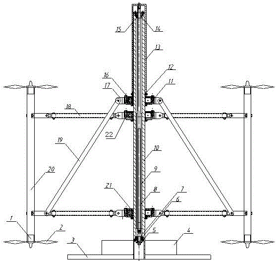
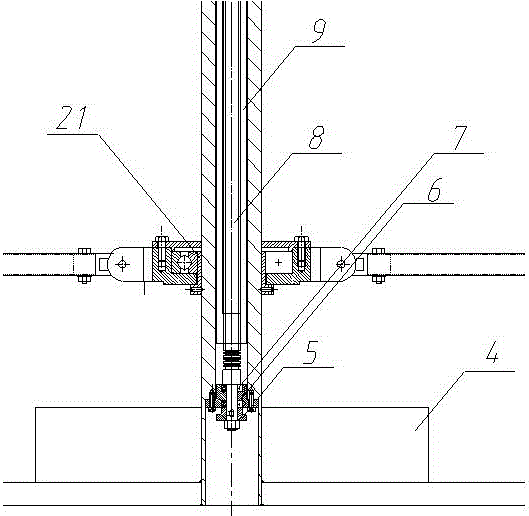
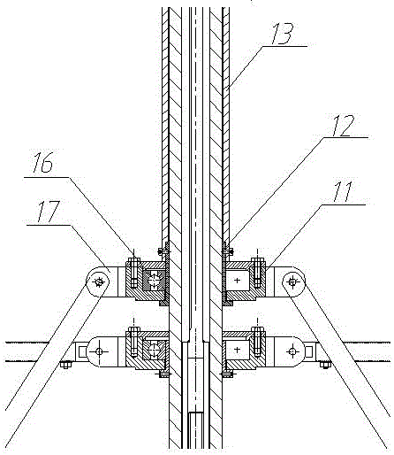
[0037] Such as Figure 1 to Figure 5 Shown is a multi-rotor UAV structure test device based on a variable-diameter frame, including a column 10, a column inner bearing mechanism, a column inner transmission mechanism, a column outer bearing mechanism, a lifting sleeve 13, a connecting rod mechanism and a motor Mounting rod 20, the internal bearing mechanism of the column and the transmission mechanism in the column are all arranged in the column 10, the outer bearing mechanism of the column is arranged on the outside of the column 10, and the motor mounting bar 20 is connected with the column through a connecting rod mechanism. 10 connections.

[0038]The inner bearing mechanism of the column includes an upper end flange 14 on the upper end, a guide key 15 and a lifting adjustment nut 5 on the lower end, a lower flange 6 and an inner bearing 7, and the transmission mechanism in the column includes mutual Socketed trapezoidal screw 8 and trapezoidal nut shaft 9, the trapezoida...


PUM


Abstract

The invention discloses a multi-rotor unmanned aerial vehicle structure testing device and method based on a variable-diameter rack. The device comprises a stand column, a stand column inner bearing mechanism, a stand column inner transmission mechanism, a stand column outer bearing mechanism, a lifting sleeve, a link mechanism and motor installing rods; the stand column inner bearing mechanism comprises an upper-end flange plate and a guide key which are arranged at the upper end and a lifting regulating nut, a lower-end flange plate and an inner bearing which are arranged at the lower end; the stand column inner transmission mechanism comprises a trapezoidal screw and a trapezoidal nut shaft, and the upper end of the trapezoidal nut shaft penetrates through the upper-end flange plate and the guide key and is connected with the top of the lifting sleeve; the stand column outer bearing mechanism comprises multiple bearings which are slidably connected to the outer side of the stand column in a sleeving mode. According to the multi-rotor unmanned aerial vehicle structure testing device and method based on the variable-diameter rack, the problem that in multi-rotor unmanned aerial vehicle structure design, part parameter matching experiment testing technological means are insufficient can be effectively solved, and a flexible, variable and effective testing means can be provided from the aspects of the diameter size of the unmanned aerial vehicle rack, the blade size of propellers, the rotor number and the arrangement mode of the propellers, the shock resistance of connection between an unmanned aerial vehicle and a cloud platform or a load and the like.

Description

technical field [0001] The invention relates to a multi-rotor unmanned aerial vehicle device, which can be used for frame structure design and performance test of the unmanned aerial vehicle in the unmanned aerial vehicle design stage. Background technique [0002] A multi-rotor UAV is a special unmanned helicopter with three or more rotor shafts, which drives the rotors to rotate through the motor on each shaft, thereby generating thrust. By changing the relative rotational speed between different rotors, the size of the single-axis propulsion can be changed, thereby controlling the trajectory of the aircraft. Compared with fixed-wing UAVs, multi-rotor UAVs have the following technical advantages: [0003] (1) Strong maneuverability. The multi-rotor UAV can take off and land vertically without a runway, and can hover in the air after takeoff. The control principle is simple, and it can control the movement of the aircraft in the forward and backward, left and right, up an...

Claims


Application Information

Patent Timeline
Patent Type & Authority Applications(China)
IPC IPC(8): B64F5/00
Inventor 孙兵
Owner IANGSU COLLEGE OF ENG & TECH
Why Eureka
Try Eureka