Counter-pulling wall connecting component

A technology of connecting wall parts and wall parts, which is applied to the accessories of scaffolding, building structure support, building structure support, etc., can solve problems such as wall damage, wall thickness limitation, and hidden safety hazards, so as to ensure turnover and increase The effect of improving reliability and versatility

Inactive Publication Date: 2016-12-21
SHANGHAI HONGJIN EQUIP & ENG CO LTD
View PDF10 Cites 5 Cited by
  • Summary
  • Abstract
  • Description
  • Claims
  • Application Information

AI Technical Summary

Problems solved by technology

However, this invention cannot prevent the concrete from contacting the pull screw from the gap between the through pipe and the formwork when the wall is poured, so that the pull screw cannot be pulled out in direct contact with the concrete, so that it cannot be used for turnover; it needs to be tightened with the help of a wrench and other tools during installation. It is laborious to operate the pull screw; the length of the pull bolt must be greater than the sum of the wall thickness and the length of the tubular cross bar. When the length of the pull screw is fixed, there is a limit to the thickness of the wall, which reduces the versatility of the pull screw; The end of the tubular cross bar vertically against the wall is not fixed to the wall. When the force perpendicular to the tubular cross bar is applied, the end of the tubular cross bar against the wall may slide, so that the tubular cross bar is no longer perpendicular to the wall, resulting in Potential safety hazard; in addition, one end of the tubular crossbar is in direct contact with the wall, and the side of the wall against which the tubular crossbar abuts may be destroyed due to excessive pressure

Method used


Image

  • Counter-pulling wall connecting component
  • Counter-pulling wall connecting component
  • Counter-pulling wall connecting component

Examples


Embodiment Construction

[0028] Below, in conjunction with the accompanying drawings, preferred embodiments of the present invention are given and described in detail, so that the functions and features of the present invention can be better understood.

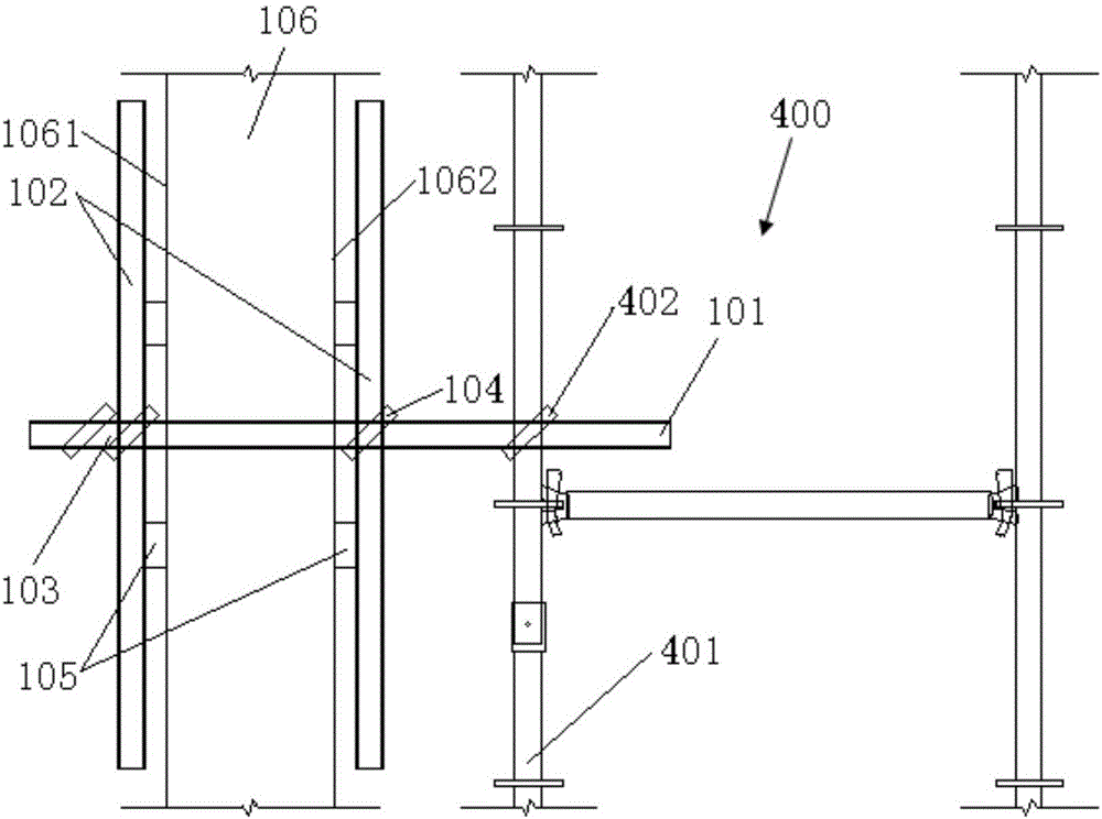
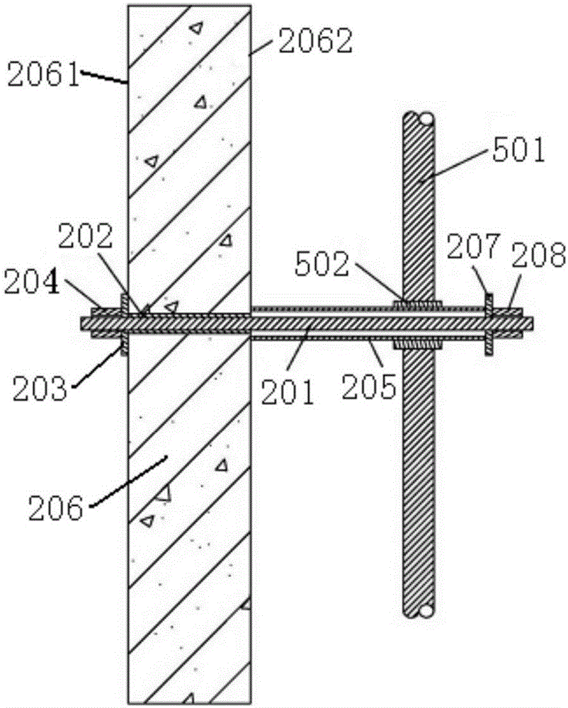
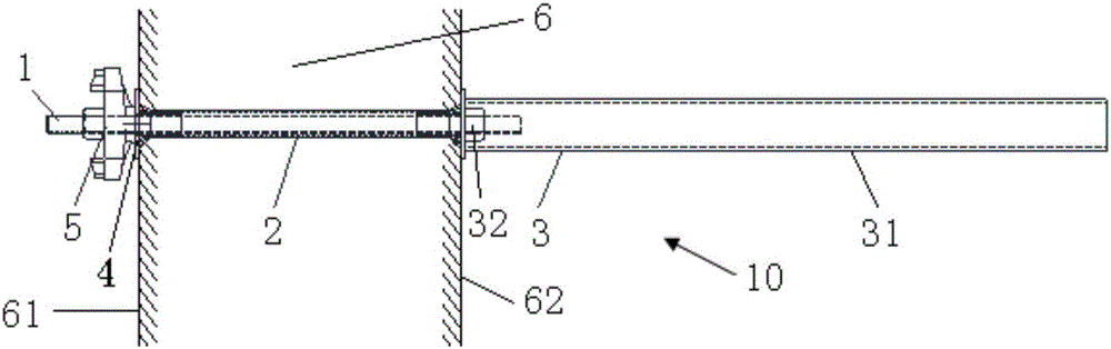
[0029] Such as image 3 with 4 Shown is a wall connecting piece 10 according to a preferred embodiment of the present invention. The wall connecting piece 10 includes a pull screw 1 which has external threads and whose two ends protrude from the inner wall surface 61 and the outer wall of the wall body 6 respectively. surface 62, and are respectively fixed at the two side walls by fastening devices; a pre-embedded pipe 2 is sleeved on the outer peripheral wall of the pull screw 1 between the inner wall surface 61 and the outer wall surface 62; a connecting wall pipe One end of the assembly 3 is fixedly connected to the part of the pull screw 1 protruding from the outer wall surface 62 , and vertically abuts against the outer wall surface 62 of the w...


PUM


Abstract

The invention provides a counter-pulling wall connecting component which comprises a counter-pulling screw with external threads. The two ends of the counter-pulling screw are in screwing fit with fastening devices correspondingly. The outer wall of the counter-pulling screw is sleeved with a hollow embedded pipe, and hollow plugs are inserted into the two ends of the embedded pipe correspondingly. The fastening device located at one end of the counter-pulling screw is composed of a gasket and a nut, and the fastening device located at the other end of the counter-pulling screw is a wall connecting tube assembly. According to the counter-pulling wall connecting component, concrete is prevented from entering the embedded pipe through the design of the plugs at the two ends of the embedded pipe, and thus the possibility of repeated utilization of the counter-pulling screw is increased, and waste of aluminum formworks is reduced. A counter-pulling screw used in the wall pouring process is certainly suitable for the wall connecting component, and the universality of the counter-pulling screw is improved. In addition, nut-gasket assemblies at the two ends of the counter-pulling screw both can be manually fastened, installation is convenient, and potential safety hazards and wall damage in assembling of the wall connecting component and a scaffold are eliminated.

Description

technical field [0001] The invention relates to scaffolding engineering in the field of construction, in particular to a pair of tensioned wall pieces for connecting scaffolding and walls. Background technique [0002] In construction projects, such as when scaffolding is built, wall-connecting parts are usually used to connect the scaffolding and the wall. The wall connection is a special rod between the scaffold and the wall, and is generally divided into flexible wall connection and rigid wall connection. Flexible wall parts generally adopt thin steel bars, ropes, double-strand or multi-strand iron wires. Rigid wall parts are composed of rigid tie rods or components such as steel pipes, fasteners or embedded parts. Conventional wall parts are usually fixed by tension-brace combination method, pre-embedded steel pipe method and post-anchor method. [0003] Such as figure 1 As shown, when the formwork construction system of the non-aluminum formwork system is traditiona...

Claims


Application Information

Patent Timeline
Patent Type & Authority Applications(China)
IPC IPC(8): E04G5/04
CPCE04G5/046
Inventor 何子明
Owner SHANGHAI HONGJIN EQUIP & ENG CO LTD
Why Eureka
Try Eureka