Pump body structure and compressor

A pump body and cavity technology, applied in the field of compressors, can solve the problems of air conditioner cooling capacity drop, high and low pressure collusion, sliding vanes and sticks are easy to detach, etc., to avoid impact noise, save costs, and prevent high and low pressure collusion Effect

Active Publication Date: 2016-12-21
GREE ELECTRIC APPLIANCES INC
View PDF5 Cites 3 Cited by
  • Summary
  • Abstract
  • Description
  • Claims
  • Application Information

AI Technical Summary

Problems solved by technology

[0004] The embodiment of the present invention provides a pump body structure and a compressor, which can solve the problem in the prior art that the sliding vane and the stick are easily detached, leading to the high and low pressure collusion in the cylinder, which causes the cooling capacity of the air conditioner to drop sharply

Method used


Image

  • Pump body structure and compressor
  • Pump body structure and compressor
  • Pump body structure and compressor

Examples


Embodiment Construction

[0023] The present invention will be described in further detail below in conjunction with the accompanying drawings and specific embodiments, but not as a limitation of the present invention.

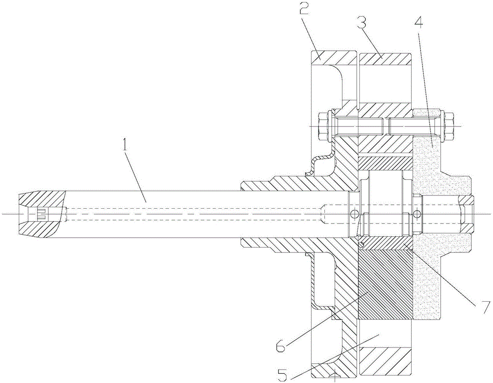
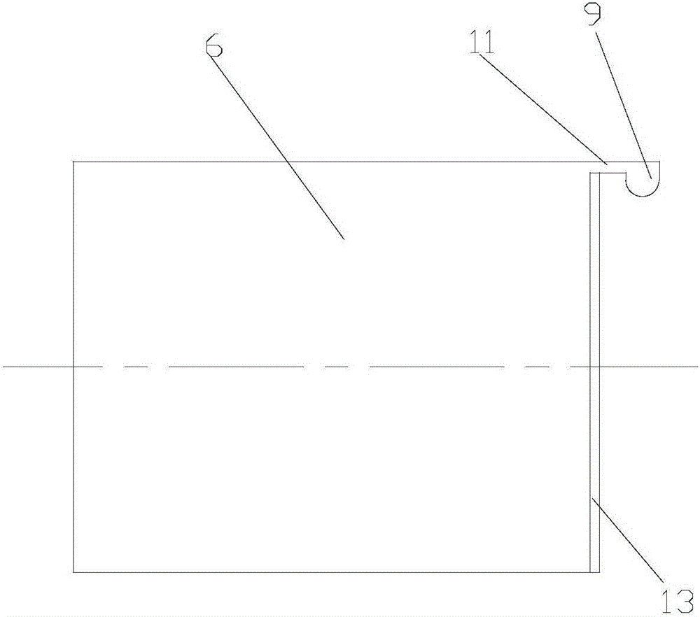
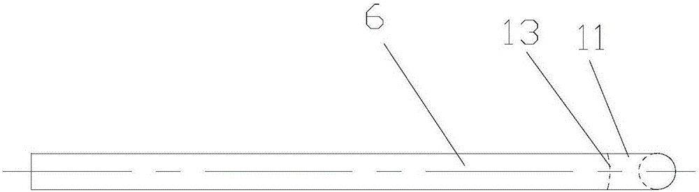
[0024] Such as Figure 1 to Figure 5 As shown, according to the embodiment of the present invention, the pump body structure includes a crankshaft 1 and an upper flange 2, a cylinder 3 and a lower flange 4 arranged in sequence along the axial direction of the crankshaft 1, and a roller 7 is arranged in the cavity of the cylinder 3, The roller 7 is sleeved outside the crankshaft 1, and the cylinder 3 is also provided with a slide groove 5, and a slide plate 6 is slidably arranged in the slide groove 5, and the other end of the slide plate 6 is connected in rotation with the roller 7.

[0025] The sliding plate 6 and the roller 7 of the pump body structure are rotatably connected, so the sliding plate 6 and the roller 7 can be kept in contact all the time, which can effectively prevent t...


PUM


Abstract

The invention discloses a pump body structure and a compressor. The pump body structure comprises a crankshaft (1), an upper flange (2), a cylinder (3) and a lower flange (4), wherein the upper flange (2), the cylinder (3) and the lower flange (4) are sequentially arranged along the axial direction of the crankshaft (1); a roller (7) is arranged inside the chamber body of the cylinder (3) and sleeves the outside of the crankshaft (1); the cylinder (3) is also provided with a sliding groove (5); a sliding plate (6) is arranged inside the sliding groove (5) in a sliding manner; the other end of the sliding plate (6) is rotationally connected with the roller (7). The pump body structure disclosed by the invention is capable of solving the problem that the refrigeration capacity of an air conditioner is reduced sharply because high pressure and low pressure in the cylinder body are mixed when the sliding plate and the roller are easily separated.

Description

technical field [0001] The invention relates to the technical field of compressors, in particular to a pump body structure and a compressor. Background technique [0002] In order to ensure that the compressor rollers and the slide vanes are always connected, the existing compressors all adopt a spring to support the tail of the slide vanes so that the heads of the slide vanes are always in contact with the rollers to maintain sealing. [0003] The existing compressor pump body structure is mainly composed of crankshaft, roller, sliding plate, upper flange, lower flange, cylinder, pump spring, muffler, etc. The crankshaft rotates under the drive of the motor, and the roller is eccentric Cooperate with the elliptical movement in the cylinder, the sliding plate is always in contact with the roller under the action of the pump spring and divides the cylinder into a high-pressure chamber and a low-pressure chamber, and the crankshaft rotates once to drive the roller to compress ...

Claims


Application Information

Patent Timeline
Patent Type & Authority Applications(China)
IPC IPC(8): F04C18/356F04C18/44F04C29/00
CPCF04C18/356F04C18/44F04C29/00
Inventor 樊峰刚彭慧明曹彭杰韩鑫金冀龙白璐琛卢林高
Owner GREE ELECTRIC APPLIANCES INC
Why Eureka
Try Eureka