Hub, sliding sleeve and synchronous device, as well as method for producing hub and method for producing sliding sleeve

A technology for sliding sleeves and synchronous equipment, which is applied in the field of manufacturing sliding sleeves and manufacturing hubs, which can solve the problems of troublesome sliding sleeves and delay the manufacturing process of sliding sleeves, and achieve the effect of simple cost

Active Publication Date: 2016-12-21
HOERBIGER ANTRIEBSTECHN HLDG
View PDF9 Cites 2 Cited by
  • Summary
  • Abstract
  • Description
  • Claims
  • Application Information

AI Technical Summary

Problems solved by technology

[0006] However, additional machining of the sliding sleeve, in particular subseq

Method used


Image

  • Hub, sliding sleeve and synchronous device, as well as method for producing hub and method for producing sliding sleeve
  • Hub, sliding sleeve and synchronous device, as well as method for producing hub and method for producing sliding sleeve
  • Hub, sliding sleeve and synchronous device, as well as method for producing hub and method for producing sliding sleeve

Examples


Embodiment Construction

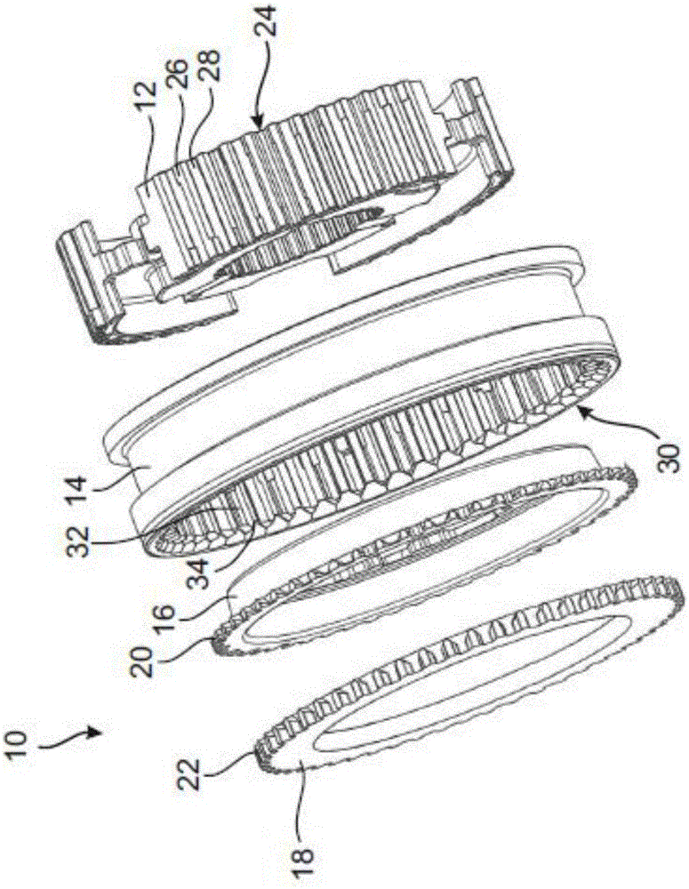
[0045] figure 1 A part of a synchronization device 10 for a gearbox of a motor vehicle is shown.

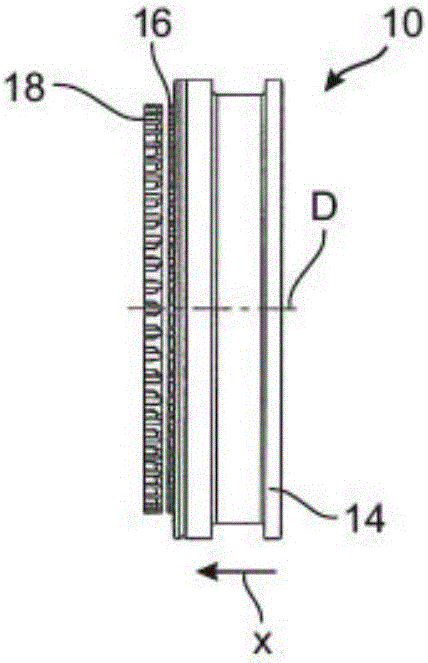
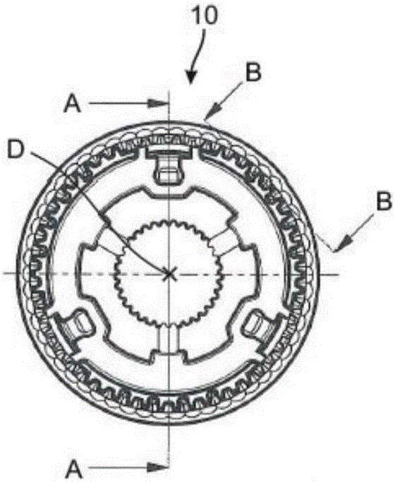
[0046] The synchronization device 10 comprises a disk-shaped hub 12 , which is seated in a rotationally fixed manner on a gear shaft and rotates about an axis of rotation D in the circumferential direction. Furthermore, the synchronization device 10 has a substantially annular sliding sleeve 14 which is arranged displaceably in the axial direction and is coupled to the hub 12 in a rotationally fixed manner. Furthermore, the synchronization device 10 has a synchronization ring 16 and a clutch body 18 which is part of an escape wheel (not shown here) which can be shifted after the rotational movements of the clutch body 18 and the hub 12 have been synchronized.

[0047] For synchronizing the rotational movement, a synchronizing ring 16 is provided, via which a frictional connection can be established between the hub 12 and the clutch body 18 or the escape wheel. To this end, the ...


PUM


Abstract

A hub (12) for a synchronous device (10) of a motor vehicle is described, wherein the hub (12) comprises an outer tooth (24) consisting of a sintered powder material and has a plurality of hub teeth (26) and tooth gaps (28) between the hub teeth. Furthermore, the hub teeth (26) have at least two hub sections (36, 38, 40) and a width varying in the axial moving direction (X). At least two hub sections (36, 38, 40) each have lateral widening parts (42, 44) which are provided on opposite sides of the hub teeth (26) in the axial moving direction (X). A sliding sleeve (14), the synchronous device (10), a method for producing the hub (12) and a method for producing the sliding sleeve (14) are also described.

Description

technical field [0001] The invention relates to a hub, a sliding sleeve and a synchronization device with a hub and a sliding sleeve. Furthermore, the invention relates to a method for producing a hub and a method for producing a sliding sleeve. Background technique [0002] Synchronization devices are known in the prior art, which are used in transmissions and have at least one hub and a sliding sleeve. In addition, a synchronizing ring and an escape wheel or a clutch body are usually arranged in a synchronous device. When the escape wheel or clutch body is to be switched, the sliding sleeve utilizes the escape wheel or clutch body to couple with the hub for rotational movement. It is known that the sliding sleeve and / or the clutch body have pawl geometry, which ensures that the sliding sleeve can only be adjusted when the rotational speeds are equalized or synchronized. In order to facilitate the insertion of the sliding sleeve into the clutch toothing of the clutch body...

Claims


Application Information

Patent Timeline
IPC IPC(8): F16D23/06B22F3/12
CPCB22F3/16F16D23/06F16D2023/0625F16D2023/0631F16D2023/0656B22F3/12B22F5/08
Inventor 维尔纳·菲尔古特
Owner HOERBIGER ANTRIEBSTECHN HLDG
Why Eureka
Try Eureka