Apparatus and method for producing a plasma, and use of such an apparatus

A plasma and equipment technology, applied in the field of plasma, can solve the problems of complex equipment construction, high energy and electric power input, etc., and achieve the effect of simple cost

Inactive Publication Date: 2018-03-27
TERRAPLASMA GMBH
View PDF7 Cites 1 Cited by
  • Summary
  • Abstract
  • Description
  • Claims
  • Application Information

AI Technical Summary

Problems solved by technology

However, due to the generally defined spatial static nature of the discharges, only relatively small volumes of plasma can be generated or fluids treated, for example, or it require

Method used


Image

  • Apparatus and method for producing a plasma, and use of such an apparatus
  • Apparatus and method for producing a plasma, and use of such an apparatus
  • Apparatus and method for producing a plasma, and use of such an apparatus

Examples


Example Embodiment

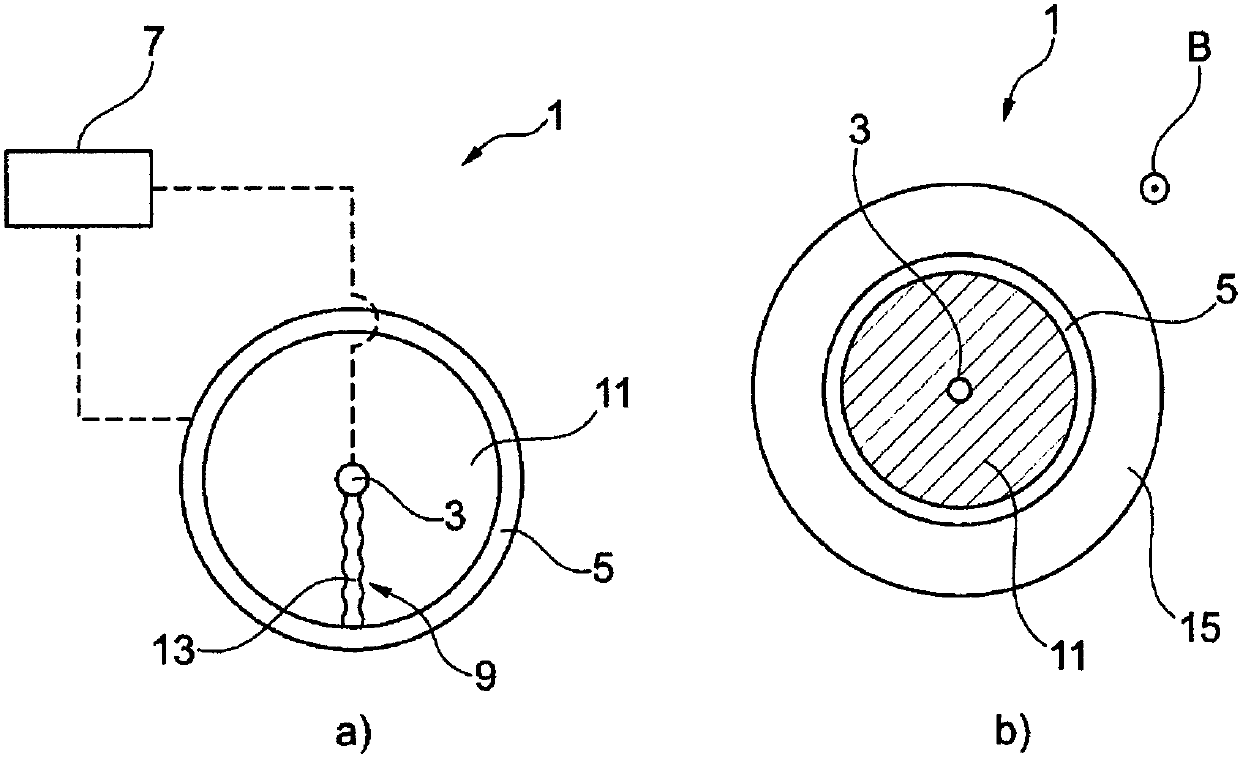
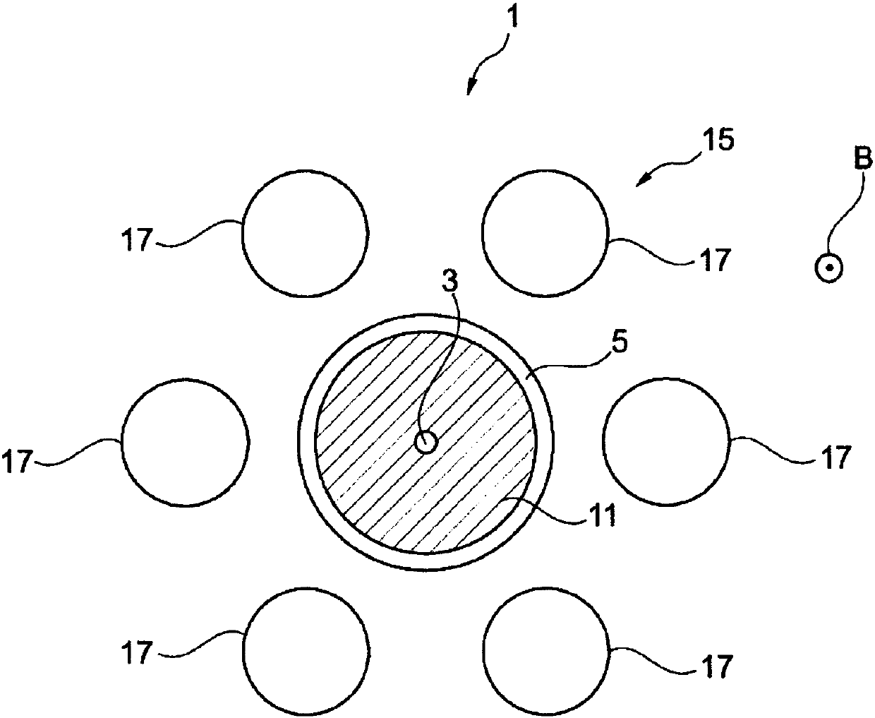
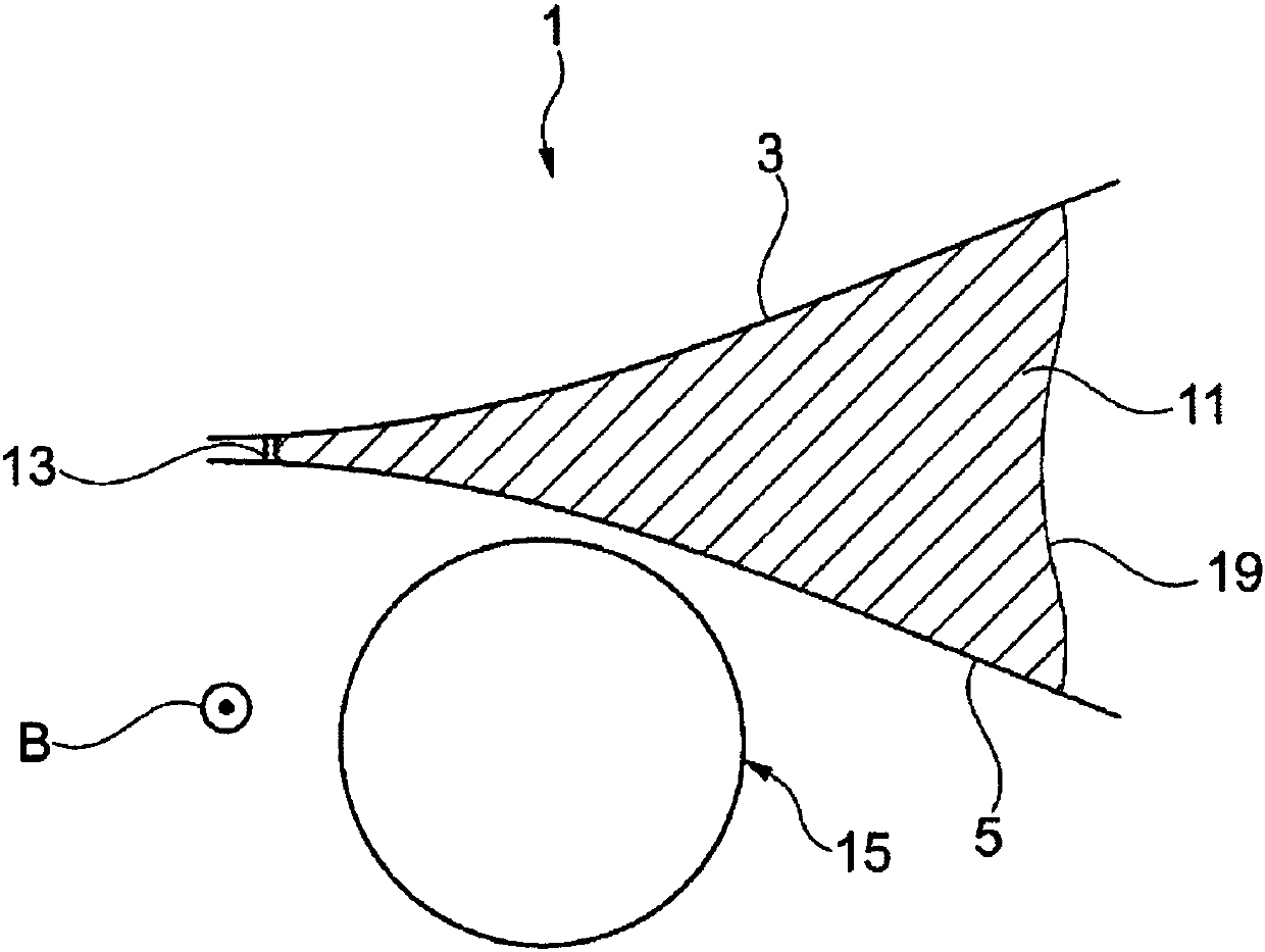
[0069] figure 1 A schematic diagram of a first embodiment of the apparatus 1 for generating plasma is shown. Here at figure 1 A) shows the device 1, which has a first electrode 3 and a second electrode 5. The first electrode 3 is formed as a rod-shaped or linear electrode, and the second electrode 5 is formed as a ring electrode, which surrounds the first electrode 3 and the second electrode 5 in the circumferential direction. One electrode 3. Here, the axial direction is perpendicular to figure 1 The image plane of a) extends, the radial direction is perpendicular to the axial direction, and is arranged in the image plane, and the circumferential direction extends concentrically around the axial direction. The first electrode 3 and the second electrode 5 are arranged spaced apart from each other.

[0070] In particular, the second electrode 5 is formed in a circular ring shape in this case, in which the first electrode 3 is arranged in the center of the circle defined by the...


PUM


Abstract

The invention relates to an apparatus (1) for producing a plasma, having at least one first electrode (3), at least one second electrode (5), which is arranged at a distance from the first electrode (3), a voltage source (7), which is connected to at least one electrode (3, 59) selected from the first electrode (3) and the second electrode (5) such that a potential difference between the at leastone first electrode (3) and the at least one second electrode (5) can be produced by the voltage source (7), wherein the at least one first electrode (3) and the at least one second electrode (5) define at least one discharge path (9) for an electrical discharge in a discharge region (11) between the at least one first electrode (3) and the at least one second electrode (5). In this case, a magnetic field device (15) is provided that is set up, and arranged relative to the at least one first electrode (3) and the at least one second electrode (5), to provide a magnetic field in the discharge region (11), so that a magnetic field vector (B) of the magnetic field is oriented at an angle to the discharge path (9).

Description

technical field [0001] The present invention relates to a device and a method for generating a plasma and to the use of such a device. Background technique [0002] Devices and methods for generating plasmas are known in principle. In such devices, usually a temporally and / or spatially static discharge between two electrodes is triggered, wherein a plasma is generated by the discharge. The device and the method, by means of which a so-called cold, non-thermal or atmospheric plasma can be generated, prove to be particularly advantageous for the disinfection or sterilization of surfaces or fluid flows and / or for the treatment of wounds. However, due to the generally defined spatial static nature of the discharges, only relatively small volumes of plasma can be generated or fluids treated, for example, or it requires multiple discharges, or large area discharges, which are related to energy and / or A correspondingly high investment in electrical power also requires complex pla...

Claims


Application Information

Patent Timeline
IPC IPC(8): H05H1/50A61L2/14
CPCA61L2/14H05H1/50A61L2202/11A61L9/22B01D53/007B01D2259/818B08B3/14B08B7/0035C02F1/30C02F2303/04
Inventor 格雷戈尔·莫非尔李阳方清水铁司贝恩德·斯特弗斯
Owner TERRAPLASMA GMBH
Why Eureka
Try Eureka