Automatic transmission with torque converter, a dnr gear group, and a cvt unit and method of operating the same

A technology of automatic transmission and gear set, applied in the direction of belt/chain/gear, transmission device, mechanical equipment, etc., can solve the problems of high cost of automatic transmission and achieve the effect of simple cost

Active Publication Date: 2012-09-12
ROBERT BOSCH GMBH
View PDF7 Cites 2 Cited by
  • Summary
  • Abstract
  • Description
  • Claims
  • Application Information

AI Technical Summary

Problems solved by technology

[0005] The drawback of the known automatic transmission is the complexit

Method used


Image

  • Automatic transmission with torque converter, a dnr gear group, and a cvt unit and method of operating the same
  • Automatic transmission with torque converter, a dnr gear group, and a cvt unit and method of operating the same
  • Automatic transmission with torque converter, a dnr gear group, and a cvt unit and method of operating the same

Examples


Example Embodiment

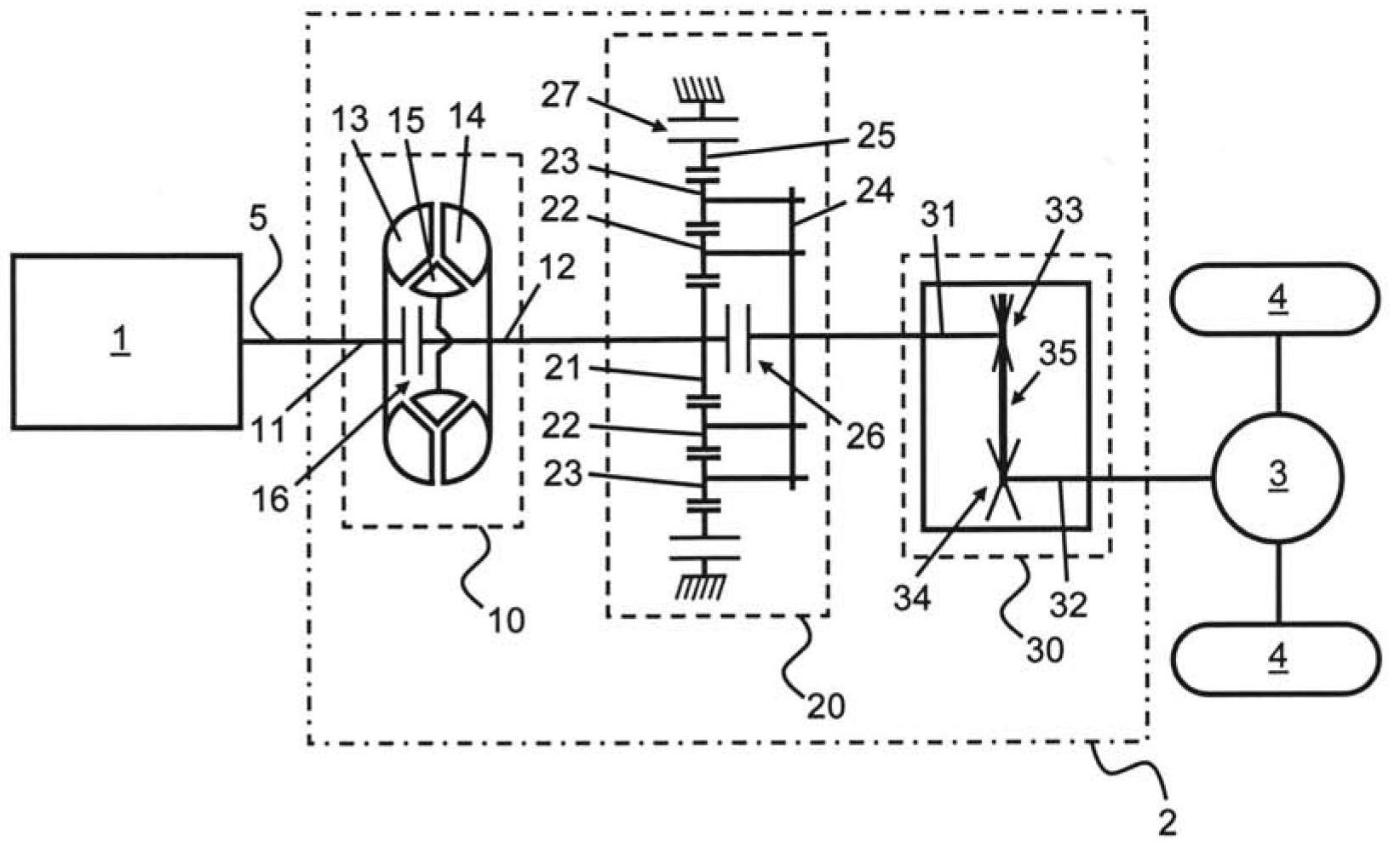
[0015] figure 1 A drive train for a vehicle is shown, with a drive engine 1, an automatic transmission 2 and two wheels 4 driven by its differential 3. In the driving direction, the known automatic transmission 2 continuously includes a torque converter 10, a shiftable drive gear-neutral-reverse or DNR gear set 2 and a continuously variable transmission or CVT unit 30. Generally, the final drive, that is to say the gear stage including two or more gears, occurs between the CVT unit 30 and the differential 3 (not shown).

[0016] The crankshaft 5 of the engine 1 is coupled to the input shaft 11 of the torque converter 10 that drives the pump wheel 13. The turbine 14 of the torque converter 10 drives its output shaft 12. In a manner known per se, the pump wheel 13 drives the turbine 14 by means of hydraulic fluid and the so-called stator 15 of the torque converter 10, in which case the driving torque from the input shaft 11 to the output shaft 12 can be increased. The torque conv...


PUM


Abstract

The invention relates to an automatic transmission (2) for transmitting a mechanical power between a driving engine and a driven load, in particular for a vehicle with an internal combustion engine. The automatic transmission (2) is provided with a torque converter (10), with a shiftable DNR gear group (20) comprising a sun wheel (41), planet gears (42) and a ring gear (43), and with a Continuously Variable Transmission unit (30), in which each planet gear (42) of the DNR gear group (20) is in engagement with both the sun wheel (41) and the ring gear (43) thereof.

Description

technical field [0001] The invention relates to an automatic transmission for transferring mechanical energy between a driving engine and a driven load, in particular for a motor vehicle with an internal combustion engine, said automatic transmission comprising, in the driving direction, a torque converter, a shiftable Drive-neutral-reverse or DNR gear set and continuously variable transmission or CVT unit. Such automatic transmissions are generally known and are described, for example, in European patent publication EP 1 939 504 A. Background technique [0002] The torque converter of this known automatic transmission is also generally known and is used to run the internal combustion engine when the vehicle is stationary and to increase the torque produced by said engine when the vehicle is accelerating, especially starting from a standstill. The nominal torque ratio of the torque converter, that is to say the ratio between the torque on the stationary output shaft of the ...

Claims


Application Information

Patent Timeline
IPC IPC(8): F16H37/02
CPCF16H37/022
Inventor P·达斯A·范德维尔S·朔尔滕
Owner ROBERT BOSCH GMBH
Why Eureka
Try Eureka