
A hollow unit body for metal 3D printing and parts with the unit body

A 3D printing and metal parts technology, which is applied in the direction of slender components, building components, acetabular sockets, etc., can solve the problems of low weight reduction ratio of parts, unreasonable hollow unit structure design, etc., and improve reliability , Avoid stress and performance differences, the effect of high weight reduction ratio

Active Publication Date: 2019-01-18
XIAN BRIGHT ADDTIVE TECH CO LTD
View PDF6 Cites 0 Cited by
  • Summary
  • Abstract
  • Description
  • Claims
  • Application Information

AI Technical Summary

Problems solved by technology

[0006] The purpose of the present invention is to provide a hollow unit body suitable for metal 3D printing technology, which solves the problem that the structure design of the existing hollow unit body is unreasonable and the weight reduction ratio of parts is not high

Method used


Image

  • A hollow unit body for metal 3D printing and parts with the unit body
  • A hollow unit body for metal 3D printing and parts with the unit body
  • A hollow unit body for metal 3D printing and parts with the unit body

Examples


Embodiment 1

[0046] Aluminum alloy hollow tensile specimens are formed by 3D printing, such as Figure 4 As shown, the specific method is:

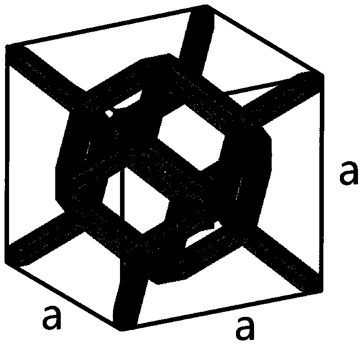
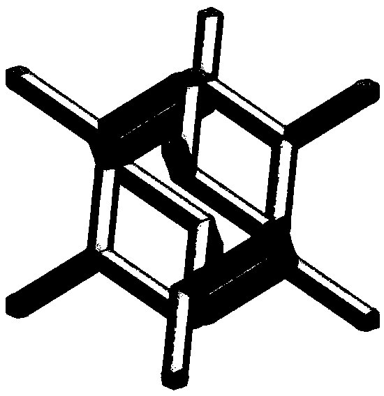
[0047]Through the existing 3D modeling software, divide the 3D model of the hollow tensile sample into the hollow area, and extract the area that needs to be hollowed out for weight reduction design; use the commercial 3D modeling software UG software to design the hollow area, and the hollow unit body The main structure is a rhombic dodecahedron, and eight extending ribs protrude outward along the diagonal of the body. The angle between each main rib and the horizontal projection surface is 35°, and the outer contour size of the extending ribs is 5mm×5mm ×5mm (such as figure 1 As shown a=5mm), the rib diameter is 0.5mm; carry out a regular three-dimensional space array of a certain direction and density on the hollowed out unit body to form a hollowed out area; combine the hollowed out area with other areas of the tensile sample to obtain the final ...

Embodiment 2

[0050] Forming a titanium alloy acetabular cup by 3D printing, such as Figure 5 As shown, the specific method is:

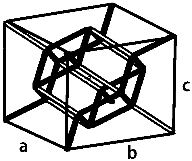
[0051] Through the existing 3D modeling software, the 3D model of the titanium alloy acetabular cup is divided into the hollow area, and the area that needs to be hollowed out for weight loss design is extracted; the hollow area is designed by using the commercial 3D modeling software UG software, and the hollowed out unit body The main structure is a rhombic dodecahedron, with eight extending ribs protruding outward along the diagonal of the body, and the angle between each main rib and the horizontal projection surface is 35°. Perform an irregular three-dimensional space array on the hollow unit body. In the process, the size and direction of the main ribs and / or extension ribs of the hollow unit body are constantly changed, but the outer contour size of the extension ribs is always guaranteed to be within Between 3mm-6mm (such as figure 1 The shown a, b, an...


PUM


Abstract

The invention discloses a hollow-out unit body suitable for the metal 3D printing technology. The hollow-out unit body comprises a main structure and an extension structure. The main structure comprises a dodecahedron structure formed by main rib strips serving as the edges. The extension structure comprises extension rib strips extending outwards from the directions of the body diagonals of a dodecahedron. The included angle between each main rib strip and the projection plane is theta, and theta is larger than or equal to 30 degrees but smaller than or equal to 90 degrees. The invention further discloses a metal part comprising the hollow-out unit body. The hollow-out unit body is of a self-supporting structure and suitable for metal 3D printing forming process conditions. Weight reduction of the unit body structure exceeds 90% maximally. A hollow-out weight reduction structure formed by the unit bodies through size changing, direction changing, density changing and other array modes is good in isotropy and high in weight reduction ratio, and the reliability of the part is improved.

Description

technical field [0001] The invention belongs to the technical field of metal additive manufacturing, and in particular relates to a hollow unit body suitable for metal 3D printing technology, and also relates to parts with the hollow unit body. Background technique [0002] The hollow weight reduction structure is formed by regular or irregular arrays of hollow unit structures in three-dimensional space. It has the characteristics of obvious weight reduction effect and excellent performance, and can meet the increasingly demanding requirements of aerospace, medical, energy, automotive and other industries. Hollow weight reduction needs. [0003] Metal 3D printing technology has rapidly developed into a new strategic direction in the field of manufacturing technology with its completely different concepts from traditional removal forming and forced forming. The specific implementation process of metal 3D printing is that the designer first draws the three-dimensional digital...

Claims


Application Information

Patent Timeline
Patent Type & Authority Patents(China)
IPC IPC(8): F16S3/08F16S3/00A61F2/34
CPCA61F2/34F16S3/00F16S3/08
Inventor 胡桥赵晓明薛蕾贺锋
Owner XIAN BRIGHT ADDTIVE TECH CO LTD
Learn More