Extractor hood

A range hood and fan technology, applied in the field of range hoods, can solve the problems of oil fume escape, poor smoke blocking effect, and inability to expand the working distance of the negative pressure area of ​​the left and right chambers of the smoke collection hood, so as to improve and reduce the range hood effect The effect of oil fume escape

Active Publication Date: 2016-12-21
NINGBO FOTILE KITCHEN WARE CO LTD
View PDF12 Cites 7 Cited by
  • Summary
  • Abstract
  • Description
  • Claims
  • Application Information

AI Technical Summary

Problems solved by technology

The deficiencies of the range hood with the above-mentioned smoke baffles mainly include: the movable smoke baffles are all flat plate structures, and because the height of the smoke collecting hood itself is limited, the movable smoke baffles that protrude up and down only have relatively The movable smoke baffle with a small extension height can be hidden in the smoke collecting hood as a whole, and the smoke baffle effect of the movable smoke baffle with a small extension height is relatively poor
For the movable smoke baffle that extends horizontally, although the wider smoke baffle can be retracted and hidden in the smoke collection hood, it cannot make the negative pressure area extend downward, and the smoke baffle effect is relatively poor
In addition, the existing movable smoke baffles are generally installed on the front of the fume collecting hood, which cannot expand the working distance of the negative pressure area of ​​the left and right chambers of the fume collecting hood, and the oil fume can easily escape from both sides

Method used


Image

  • Extractor hood
  • Extractor hood
  • Extractor hood

Examples


Embodiment Construction

[0026] The present invention will be further described in detail below in conjunction with the accompanying drawings and embodiments.

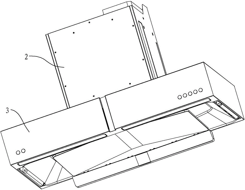
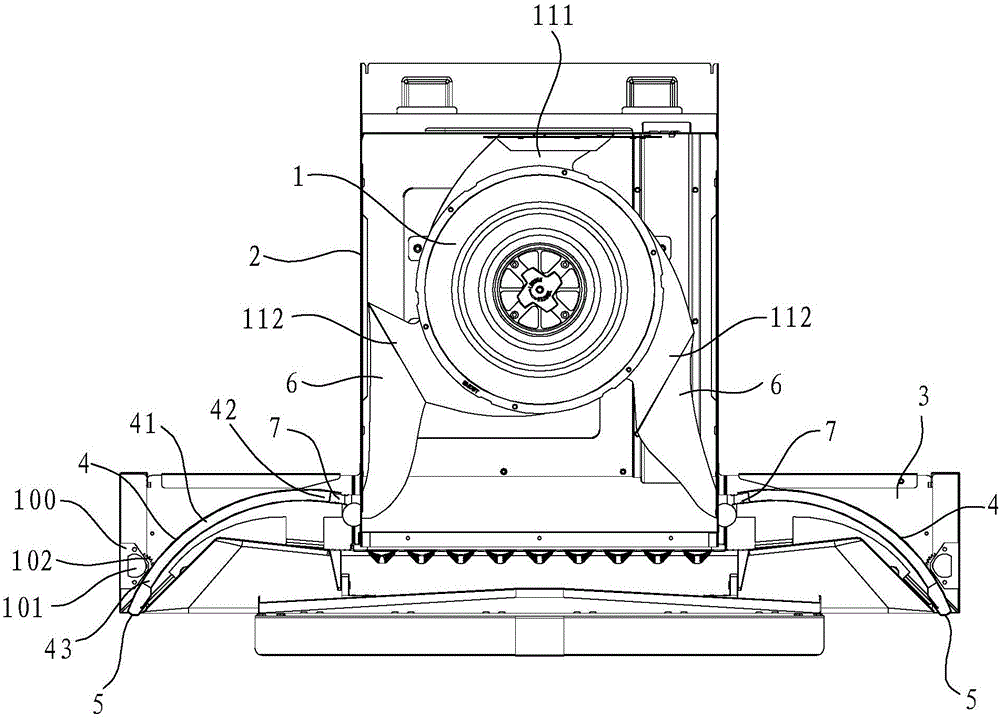
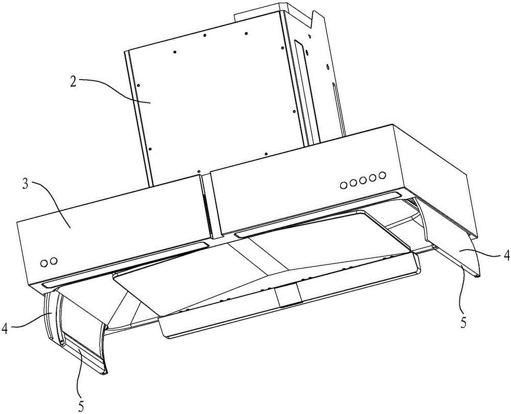
[0027] Such as Figure 1 to Figure 10 As shown, the range hood in this embodiment includes a fan 1 , a fan cover 2 and a smoke collection hood 3 , the fan 1 is arranged inside the fan cover 2 , and the smoke collection hood 3 is arranged below the fan cover 2 . The volute 11 of the blower fan 1 has a main air outlet 111 and two auxiliary air outlets 112, the main air outlet 111 is provided on the top of the volute 11, and the auxiliary air outlets 112 are respectively arranged on the left and right sides of the volute 11. An air outlet cover 6 is installed at the tuyere 112 . Movable smoke baffles 4 are installed on the left and right sides of the smoke collecting hood 3, and the movable smoke baffles 4 can extend downwards to the outside of the smoke collecting hood 3 or retract upwards to the smoke collecting hood 3 under the drive of the d...


PUM

PropertyMeasurementUnit
Gap widthaaaaaaaaaa

Abstract

An extractor hood comprises a fan, a fan outer cover and an exhaust fume collecting hood. The fan comprises a volute with a main air outlet, auxiliary air outlets are formed in the left side and the right side of the volute, movable smoke baffles are mounted on the left side and the right side of the exhaust fume collecting hood, the movable smoke baffles can stretch downwards out of the exhaust fume collecting hood or retract upwards back into the exhaust fume collecting hood, airflow cavities are formed in the movable smoke baffles, an upper air inlet and a lower air outlet are formed in the upper side and the lower side of each airflow cavity respectively, each upper air inlet is communicated with the auxiliary air outlet in the corresponding side, and each lower air outlet is provided with a nozzle with a vertically or obliquely upward injection opening. The extractor hood has the advantages that according to the extractor hood, the movable smoke baffles are driven by a driving mechanism to rotate around the exhaust fume collecting hood, the movable smoke baffles retract when not working and are unfolded to stretch out when working, negative pressure distribution extends downwards, escaping rising cooking fumes are reduced, after the injection openings are formed upwards, airflow injected by the nozzles can achieve a jetting and injection effect, and therefore part of cooking fumes about to escape below the exhaust fume collecting hood is drawn back.

Description

technical field [0001] The invention relates to a range hood. Background technique [0002] At present, the overall installation height of the European-style range hood determines that the range hood is far away from the pot that produces the oil fume, and the negative pressure loss is relatively large. Also, traditional range hoods cannot suck the fumes back once they leave the area. In order to improve the range hood effect of the range hood, people have improved the structure of the range hood, and the usual method is to improve the fan system of the range hood, such as increasing the power of the fan, such as improving the structure of the impeller, etc. etc. Although this improvement can effectively improve the range hood's range hood effect, it needs to improve the structure of the entire fan system, which is not only more complicated, but also cannot improve the distribution of the negative pressure area when the range hood is working, and the negative pressure loss ...

Claims


Application Information

Patent Timeline
IPC IPC(8): F24C15/20
CPCF24C15/20F24C15/2028F24C15/2071
Inventor 诸永定何立博茅忠群申志贤
Owner NINGBO FOTILE KITCHEN WARE CO LTD
Why Eureka
Try Eureka