Power Transformer Lifting Mounting Frame

A power transformer and lift-type technology, which is applied in the direction of transformer/reactor installation/support/suspension, etc., can solve the problems of inconvenient installation, inconvenient maintenance, installation positioning and disassembly, etc., so as to prevent position change and drop impact effect

Inactive Publication Date: 2018-08-21
STATE GRID CORP OF CHINA +1
View PDF5 Cites 0 Cited by
  • Summary
  • Abstract
  • Description
  • Claims
  • Application Information

AI Technical Summary

Problems solved by technology

[0002] At present, with the development of the times and the advancement of science and technology, people's living standards are getting higher and higher, and people's requirements for power installation equipment are getting higher and higher; power transformers are a common type of power equipment, and power transformers are installed Sometimes a mounting frame is needed, but most of the existing mounting frames are simple brackets. When the power transformer is positioned and installed, it needs the cooperation of the hoisting equipment. During the experiment, the installation, positioning and disassembly of the power transformer are particularly unchanged, so we need a new installation frame

Method used


Image

  • Power Transformer Lifting Mounting Frame
  • Power Transformer Lifting Mounting Frame
  • Power Transformer Lifting Mounting Frame

Examples


Embodiment Construction

[0017] The following will clearly and completely describe the technical solutions in the embodiments of the present invention with reference to the accompanying drawings in the embodiments of the present invention. Obviously, the described embodiments are only some, not all, embodiments of the present invention. Based on the embodiments of the present invention, all other embodiments obtained by persons of ordinary skill in the art without making creative efforts belong to the protection scope of the present invention.

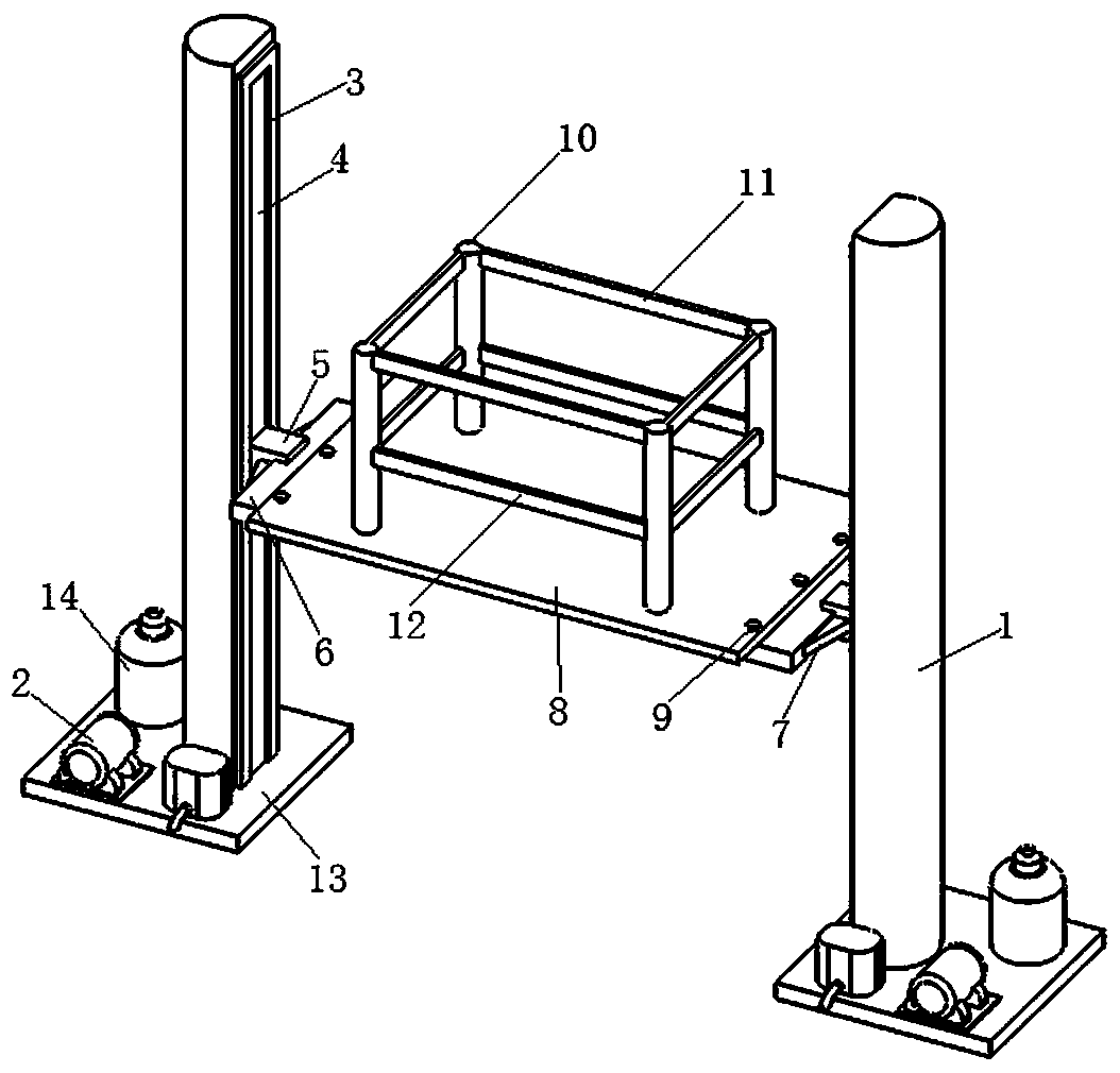
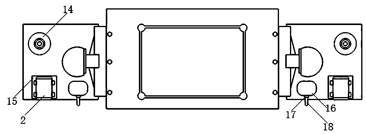
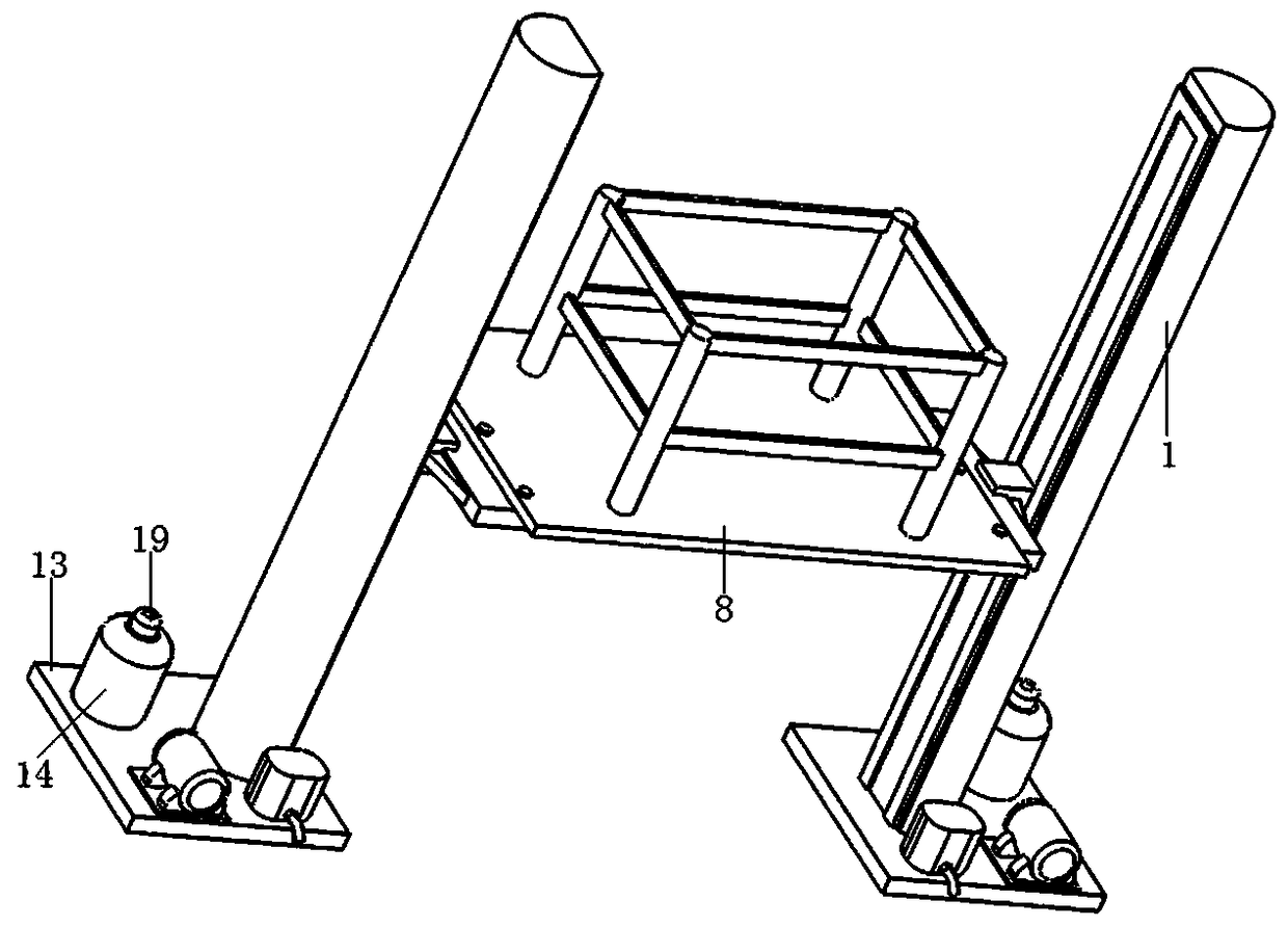
[0018] see Figure 1-3 , the present invention provides a technical solution: including two bottom plates 13; the position of the middle of the bottom surface of the bottom plate 13 close to one side is connected with a hydraulic column 1; the connection method between the hydraulic column 1 and the bottom plate 13 is welding; The opposite sides of the two hydraulic columns 1 are planes; the middle position of the plane of the hydraulic column 1 is provided wi...


PUM


Abstract

The invention discloses a lift type mounting rack for power transformers. The lift type mounting rack comprises two bottom plates. A hydraulic upright column is connected to the middle of the bottom surface of each bottom plate and is close to a side of the bottom plate; planes are arranged on opposite side surfaces of the two hydraulic upright columns; slide grooves are formed in the middles of the planes of the hydraulic upright columns; hydraulic oil cavities are arranged inside the hydraulic upright columns; friction plates are arranged outside the peripheries of the slide grooves; hydraulic lifting blocks are arranged in the slide grooves; extension connecting plates are connected with the side surfaces, which are far away from the hydraulic upright columns, of the hydraulic lifting blocks; each side of the bottom surface of a transformer supporting plate is connected with the top surface of the corresponding extension connecting plate and is close to a side of the extension connecting plate; four positioning columns are respectively mounted on the top surface of the transformer supporting plate and are close to four corners of the transformer supporting plates; a hydraulic energy accumulator is mounted on the top surface of each bottom plate and is positioned on a side of the front surface of the corresponding hydraulic upright column. The lift type mounting rack has the advantages that the transformer supporting plate can be lifted, accordingly, the lift type mounting rack can bring convenience for mounting and maintaining the power transformers, and experimental detection on the power transformers can be facilitated.

Description

technical field [0001] The invention relates to the technical field of electric power installation equipment, in particular to a power transformer lift-type installation frame. Background technique [0002] At present, with the development of the times and the advancement of science and technology, people's living standards are getting higher and higher, and people's requirements for power installation equipment are getting higher and higher; power transformers are a common type of power equipment, and power transformers are installed Sometimes a mounting frame is needed, but most of the existing mounting frames are simple brackets. When the power transformer is positioned and installed, it needs the cooperation of the hoisting equipment. During the experiment, the installation, positioning and disassembly of the power transformer are particularly unchanged, so we need a new installation frame. Contents of the invention [0003] The purpose of the present invention is to ...

Claims


Application Information

Patent Timeline
Patent Type & Authority Patents(China)
IPC IPC(8): H01F27/06
CPCH01F27/06
Inventor 刘华于洋孙建涛孙志翔王芳郑伟刘国强张一荻陶志海赵鑫张黎明范丽佟静刘荣华赵晓洁孙丽李峰张蕊
Owner STATE GRID CORP OF CHINA
Why Eureka
Try Eureka