High current usb Type C socket
A high-current, socket technology, applied in circuits, electrical components, coupling devices, etc., can solve the problems of short circuit of metal mid-plate and difficult high current passing, and achieve the effect of reducing impedance and enhancing current passing.
- Summary
- Abstract
- Description
- Claims
- Application Information
AI Technical Summary
Problems solved by technology
Method used
Image
Examples
Embodiment 1
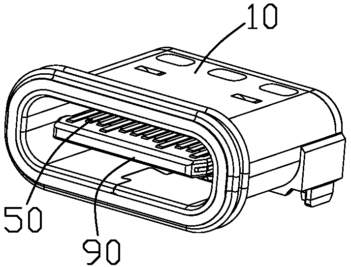
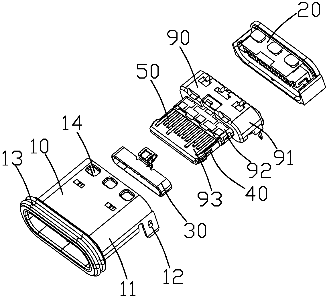
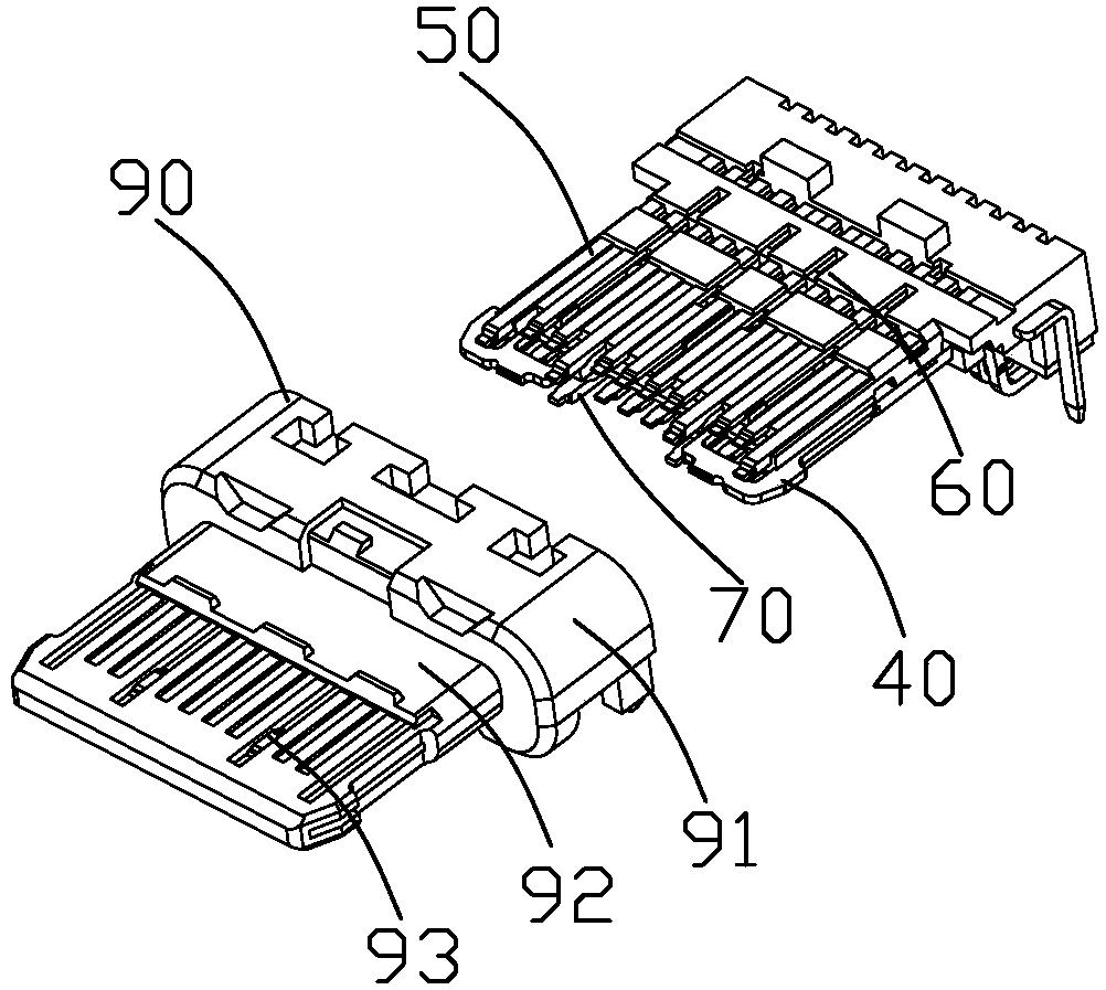
[0039] The following will combine Figure 1-Figure 15 The technical solution and technical principle of Embodiment 1 of the present application are introduced in detail.
[0040] see Figure 1 to Figure 4 As shown, the high-current USB Type C socket of the present application includes a metal middle plate 40, a first terminal group 50 located on the upper and lower sides of the metal middle plate 40, a second terminal group 70, and the first terminal group 50 and the second terminal group 70. The metal middle plate 40 is formed on the integral first insulator 60, and the second insulator 80 formed on the second terminal group 70 (such as Figure 12 shown), the third insulator 90 formed by forming the first insulator 60 and the second insulator 80 as a whole, the grounding member 30 sleeved on the third insulator 90, and the third insulator 90 surrounding the third The metal shell 10 outside the insulator 90 and the fourth insulator 20 integrally formed at the rear end of the...
Embodiment 2
[0063] see Figure 16 , Figure 17Compared with the first embodiment, the second embodiment of the present application shown is different from the second embodiment in that: the strip-shaped hole 42 on the metal middle plate 40 is penetrated in the insertion direction, so that the metal middle plate The 40-fold division is divided into a completely independent middle body part 41b and two side body parts 41a. At this time, the front ends of the first and second power terminals 50b, 70b do not need to be provided with groove structures, and there is no risk that the first and second power terminals 50b, 70b are too close to the metal middle plate 40 .
[0064] But at this time, what needs to be changed is that during the stamping process of the metal middle plate 40, the middle body part 41b and the two side body parts 41a are separately connected to the front strip of the metal middle plate 40 48 can solve the problem of strip connection caused by the separation of the midd...
Embodiment 3
[0066] see Figure 18 to Figure 20 Compared with the first embodiment, the third embodiment of the present application shown is different from the third embodiment in that: the front connecting portion 44 of the strip hole 42 of the metal middle plate 40 is cut off, and only the rear connecting portion 43 is reserved. And the rear end connecting portion 43 does not need to be thinned to form a concave portion.
[0067] The first power terminal 50b is bent upwards at the rear connecting portion 43 and then extends in parallel. The first power terminal 50b is located in front of the rear connecting portion 43 to form an upward fold A bent portion 57 and a parallel extending portion 58 extending from the upward bent portion 57 . The upwardly bent portion 57 and the parallel extending portion 58 are located on the holding portion 52 . Thus, the distance between the parallel extending portion 58 and the rear connecting portion 43 will be increased, and the upper part of the holdi...
PUM
 Abstract
Description
Claims
Application Information
 - R&D
- Intellectual Property
- Life Sciences
- Materials
- Tech Scout
- Unparalleled Data Quality
- Higher Quality Content
- 60% Fewer Hallucinations
Browse by: Latest US Patents, China's latest patents, Technical Efficacy Thesaurus, Application Domain, Technology Topic, Popular Technical Reports.
© 2025 PatSnap. All rights reserved.Legal|Privacy policy|Modern Slavery Act Transparency Statement|Sitemap|About US| Contact US: help@patsnap.com


