Permanent magnetism traction motor for subway

A traction motor, permanent magnet technology, applied in electrical components, electromechanical devices, electric components, etc., can solve the problems of poor cooling performance, poor operation reliability, and large size of permanent magnet motors, and achieve the effect of ingenious design and reasonable structure

Active Publication Date: 2016-12-21
CRRC YONGJI ELECTRIC CO LTD
View PDF10 Cites 7 Cited by
  • Summary
  • Abstract
  • Description
  • Claims
  • Application Information

AI Technical Summary

Problems solved by technology

[0003] In order to solve the problems of poor cooling performance, limited application range, poor operation reliability, complex struc

Method used


Image

  • Permanent magnetism traction motor for subway

Examples


Embodiment Construction

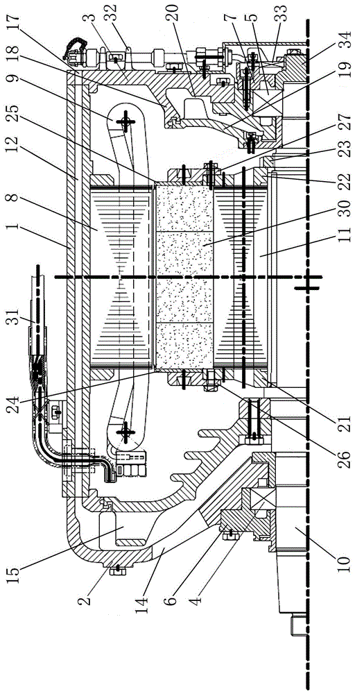
[0018] A permanent magnet traction motor for subways, comprising a front end cover 2, a rear end cover 3, a front bearing 4, a rear bearing 5, a front bearing cover 6, a rear outer bearing cover 7, a stator structure, and a rotor structure; the stator structure includes a machine Seat 1, stator core 8, stator winding 9; the stator winding 9 is embedded on the stator core 8; the rotor structure includes a rotating shaft 10, a rotor core 11, a front rotor pressure ring 21, a rear rotor pressure ring 22, a round nut 23, The front permanent magnet baffle 24, the rear permanent magnet baffle 25, the front permanent magnet baffle pressure ring 26, the rear permanent magnet baffle pressure ring 27; the rotor core 11 is fixedly assembled in the middle of the outer surface of the rotating shaft 10;

[0019] The end face of the machine base 1 is provided with an axial ventilation hole 12; the front end face of the machine base 1 is fixed to the front end cover 2; the rear end face of the...


PUM


Abstract

The invention relates to a permanent magnetism motor and concretely relates to a permanent magnetism traction motor for subway. The problems of poor cooling performance, a limited range of application, poor operational reliability, a complex structure and a large column of a present permanent magnetism motor are solved. The permanent magnetism traction motor for subway comprises a front end cover, a back end cover, a front bearing, a back bearing, a front bearing cover, a back outer bearing cover, a stator structure, and a rotor structure. The rotor structure comprises a rotation shaft, a rotor iron core, a front rotor clamping ring, a back rotor clamping ring, a circular nut, a front permanent magnet baffle plate, a back permanent magnet baffle plate, a front permanent magnet baffle plate clamping ring, and a back permanent magnet baffle plate clamping ring. A main cooling air path structure is formed by an axial direction air inlet, an axial direction air vent, an axial direction exhaust vent. An auxiliary cooling air path structure is formed by a ventilation chamber. A leading-out wire, horizontal heat radiating ribs are a rotary transformer are also comprised. The invention is suitable for a subway driving system.

Description

technical field [0001] The invention relates to a permanent magnet motor, in particular to a permanent magnet traction motor for subways. Background technique [0002] With the improvement of the performance of permanent magnet materials and the development of power electronics technology, permanent magnet motors have become the research and development direction of subway drive systems due to their high efficiency, energy saving, high power density, high starting torque and high climbing ability. However, practice shows that the existing permanent magnet motors have the following problems due to the limitations of their cooling structure and rotor structure: First, the cooling structure of the existing permanent magnet motors mainly adopts a self-contained fan cooling method (the rotating shaft drives the fan to pass the cooling wind through the windshield. holes blow to the heat dissipation ribs on the outer surface of the machine base, and then take away the heat generate...

Claims


Application Information

Patent Timeline
IPC IPC(8): H02K5/20H02K9/04H02K9/06
CPCH02K5/20H02K9/04H02K9/06
Inventor 贾喜勤侯晓军陈爱丽姬春霞倪伟吴楠刘永强
Owner CRRC YONGJI ELECTRIC CO LTD
Why Eureka
Try Eureka