
Combustion device with controllable output heat source temperature

A technology of combustion device and heat source temperature, applied in the direction of burner, combustion type, combustion method, etc., can solve the problems of limited improvement effect of combustion efficiency, small combustion range, increase device cost, etc., to achieve combustion efficiency, energy saving and environmental protection, combustion The effect of maximizing efficiency and reducing equipment cost

Inactive Publication Date: 2019-01-11
NAT CHIN YI UNIV TECH +1
View PDF6 Cites 0 Cited by
  • Summary
  • Abstract
  • Description
  • Claims
  • Application Information

AI Technical Summary

Problems solved by technology

However, no matter which method is used, the structure of the combustion device itself will be more complicated, and the spark is used to generate sparks for ignition. In addition to increasing the cost of the device, the combustion range is relatively small, and the effect on improving the combustion efficiency is quite limited, resulting in fuel waste
[0003] In addition, the temperature of the heat source after the combustion of the existing combustion device cannot be controlled, which makes it difficult to control the quality of the process and cannot ensure the quality of the manufactured products

Method used


Image

  • Combustion device with controllable output heat source temperature
  • Combustion device with controllable output heat source temperature
  • Combustion device with controllable output heat source temperature

Examples


Embodiment Construction

[0020] The structure and effect of the present invention will be described in detail by citing the following embodiments in conjunction with the accompanying drawings.

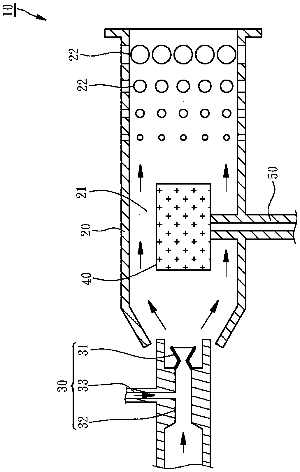
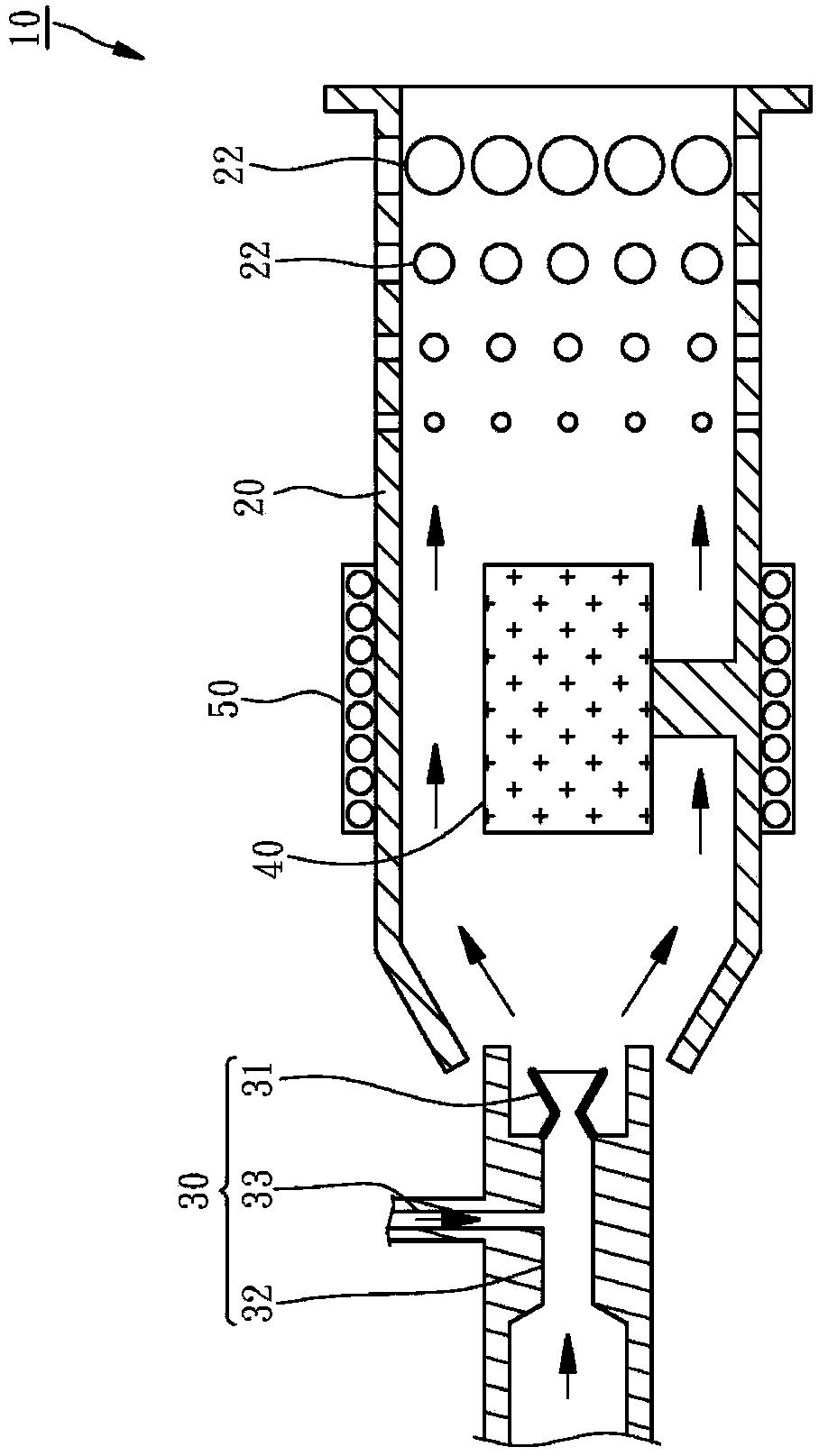
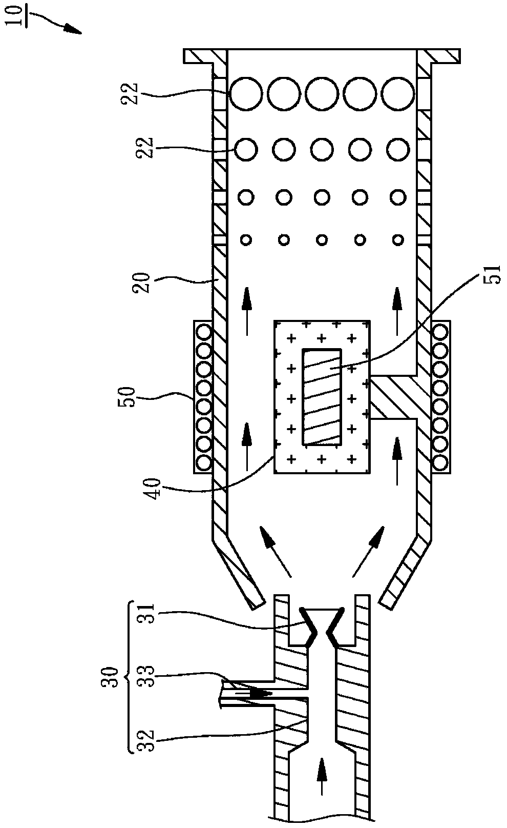
[0021] In order to better understand the characteristics of the present invention, the preferred embodiment of the present invention provides a combustion device 10 with controllable output heat source temperature, such as figure 1 As shown, it includes an igniter 40 disposed inside a first combustion chamber 20 , and a heating unit 50 disposed within the first combustion chamber 20 .

[0022] The first combustion chamber 20 is arranged in a tubular shape with openings at both ends. A fuel supplier 30 is arranged at one end opening of the first combustion chamber 20 . The first combustion chamber 20 is provided with a plurality of Through hole 22. In addition, the fuel supplier 30 has a fuel nozzle 31 , a fuel passage 32 connected to the fuel nozzle 31 , and a gas passage 33 communicating with a middle sectio...


PUM


Abstract

The invention relates to a combustion apparatus capable of controlling the temperature of an output heat source. The combustion apparatus includes an igniter which is made from a high temperature resistance material having a high-energy density and is arranged in a first combustion chamber, a heating unit which is arranged outside the first combustion chamber and is used to heat the igniter to allow the temperature of a surface of the igniter to be higher than a fire point of an atomized fuel; a mixer which is arranged on the outer periphery of the first combustion chamber, has a second combustion chamber arranged on the outer periphery of a flame outlet of the first combustion chamber, and is used for supplying gas. Accordingly, the atomized fuel can contact the surface of the igniter in the first combustion chamber, and is ignited and combusts instantly, and then the atomized fuel enters the second combustion chamber, the vaporization of the fuel is completed, the combustion efficiency is maximized, and the temperature of the output heat source is adjusted through a gas supplying action of the mixer.

Description

technical field [0001] The present invention relates to a combustion device, in particular to a combustion device that uses a high-energy-density igniter to ignite atomized fuel, and can be equipped with a mixer with at least one second combustion chamber, which can increase the combustion efficiency when replenishing air. Maximize, at the same time control the output heat source temperature. Background technique [0002] Combustion devices are widely used in kitchen stoves or boiler heating equipment in factories. At present, the traditional methods of improving combustion efficiency can be roughly divided into two types. One is to try to control the mixing ratio and uniformity of liquefied fuel and air so that the liquefied fuel To be able to burn fully, another approach is to preheat the liquefied fuel to make the liquefied fuel easier to burn. However, no matter which method is used, the structure of the combustion device itself will be more complicated, and the spark i...

Claims


Application Information

Patent Timeline
Patent Type & Authority Patents(China)
IPC IPC(8): F23D11/00F23D11/40F23D11/44F23D11/36F23D11/42F23D11/38
CPCF23D11/00F23D11/36F23D11/38F23D11/40F23D11/42F23D11/44
Inventor 翁国亮林金龙林世伟翁翎华曾钰琦
Owner NAT CHIN YI UNIV TECH
Learn More