Bending equipment used for machining copper pipe

A copper tube and equipment technology, applied in the field of bending equipment, can solve the problems of end material waste, difficult sealing, and fixing difficulties, and achieve the effect of reducing the waste of copper tubes

Inactive Publication Date: 2017-01-04
安溪县桃舟乡同盛茶叶专业合作社
View PDF4 Cites 1 Cited by
  • Summary
  • Abstract
  • Description
  • Claims
  • Application Information

AI Technical Summary

Problems solved by technology

[0002] The texture of the copper pipe is relatively hard. During processing, it is usually a fixed straight pipe structure. In order to avoid the problem of difficult sealing caused by the need for multi-section flanges and other structures to connect the pipe, the straight pipe can be bent. The hard problem is difficult to fix, and in the bending process, it is usually necessary to save a certain margin. After the bending is completed, the excess part is cut off, resulting in waste of material at the end

Method used


Image

  • Bending equipment used for machining copper pipe
  • Bending equipment used for machining copper pipe
  • Bending equipment used for machining copper pipe

Examples


Embodiment 1

[0031] In this embodiment, in order to improve the accuracy of drilling, preferably, a through hole is provided in the middle of the support block 110, and the axis of the drilling device 113 and the axis of the through hole on the support block 110 coincide with each other. The drilling operation can be realized by using a drill bit or laser drilling. After the drilling device penetrates the copper pipe, a positioning device can be set in the through hole to position the drilling depth.

Embodiment 2

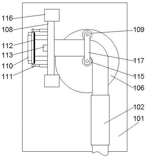
[0033] Such as Figure 4 As shown, in this embodiment, a preferred structure of a drilling device liftable structure is disclosed at the same time. Preferably, two brackets 116 are arranged on the frame 101, so that the brackets are perpendicular to the upper end surface of the frame, The upper ends of the two described supports 116 are connected to each other by cross beams 108, so that the upper ends of the supports are connected to each other, which can improve the stability of the supports, and a support that can slide vertically relative to the described supports 116 is arranged between the two described supports 116. plate 105, so that both ends of the support plate are slidably connected to the same side of the two brackets, and the drilling device 113 is fixedly connected to the support plate 105, so that the drilling device is located in the middle of the support plate. When the two brackets move longitudinally, the drilling device is driven to move synchronously, and...


PUM


Abstract

The invention discloses bending equipment used for machining a copper pipe. The bending equipment comprises a rack, a conveying device and a bending device, wherein the conveying device and the bending device are arranged above the rack. The conveying device comprises a positioning pipe and gears arranged on the two sides of the positioning pipe. Through grooves are formed in the two sides of the positioning pipe. The rack is provided with a gear drive motor and a speed reduction box matched with the gear drive motor. The gears are arranged on an output shaft of the speed reduction box in a sleeving manner. When the gears rotate, the outer circumferences of the gears are located on the inner sides of the through grooves of the positioning pipe. According to the bending equipment, the copper pipe can be directionally and stably conveyed, further bending operation is conducted, and the structure is simple; and in addition, end portion waste generated by bending is less, and more materials are saved.

Description

technical field [0001] The invention relates to a bending equipment for copper pipe processing. Background technique [0002] The texture of the copper pipe is relatively hard. During processing, it is usually a fixed straight pipe structure. In order to avoid the problem of difficult sealing caused by the need for multi-section flanges and other structures to connect the pipe, the straight pipe can be bent. For the hard problem, it is difficult to fix, and during the bending process, it is usually necessary to save a certain margin. After the bending is completed, the excess part is cut off, resulting in waste of end material. Contents of the invention [0003] The purpose of the present invention is to provide a bending equipment for copper pipe processing, which can improve the problems existing in the prior art, enable the copper pipe to be transported in a stable direction, and perform further bending operations. The structure is simple, and the bending occurs The en...

Claims


Application Information

Patent Timeline
Patent Type & Authority Applications(China)
IPC IPC(8): B21D7/06B21D43/08B23P23/04
CPCB21D7/06B21D43/08B23P23/04
Inventor 张海烽
Owner 安溪县桃舟乡同盛茶叶专业合作社
Why Eureka
Try Eureka