
A horizontal spot welding device for welding the end of a bracket lamp

A technology of spot welding device and bracket lamp, which is applied in the direction of welding/welding/cutting items, welding equipment, resistance welding equipment, etc. It can solve the problems of slow welding speed of manual holding parts, inability to automatically spot weld, and affect quality, etc., and achieves improvement. Welding quality and welding efficiency, good market development value, and the effect of reducing labor intensity

Active Publication Date: 2018-08-24
SUZHOU HAGONG YIKE ROBOT CO LTD
View PDF9 Cites 0 Cited by
  • Summary
  • Abstract
  • Description
  • Claims
  • Application Information

AI Technical Summary

Problems solved by technology

[0002] like figure 1 The bracket lamp shown has a special structure at the end, the welding point is too close to the end, and the relative position between the welding points is too small. The current vertical spot welding machine cannot perform automatic spot welding on it, and can only rely on manual holding. The parts are spot welded on a vertical spot welding machine; manual spot welding, spot welding positions are different, spot welding depths are different, missing welding and missing welding occur from time to time, which will inevitably affect the quality, and the welding speed of manual holding parts is slow and inefficient , the work is cumbersome, and the labor intensity is high; with the continuous advancement of national industrialization and informatization, this welding method can no longer meet the actual needs of the market

Method used


Image

  • A horizontal spot welding device for welding the end of a bracket lamp
  • A horizontal spot welding device for welding the end of a bracket lamp
  • A horizontal spot welding device for welding the end of a bracket lamp

Examples


Embodiment

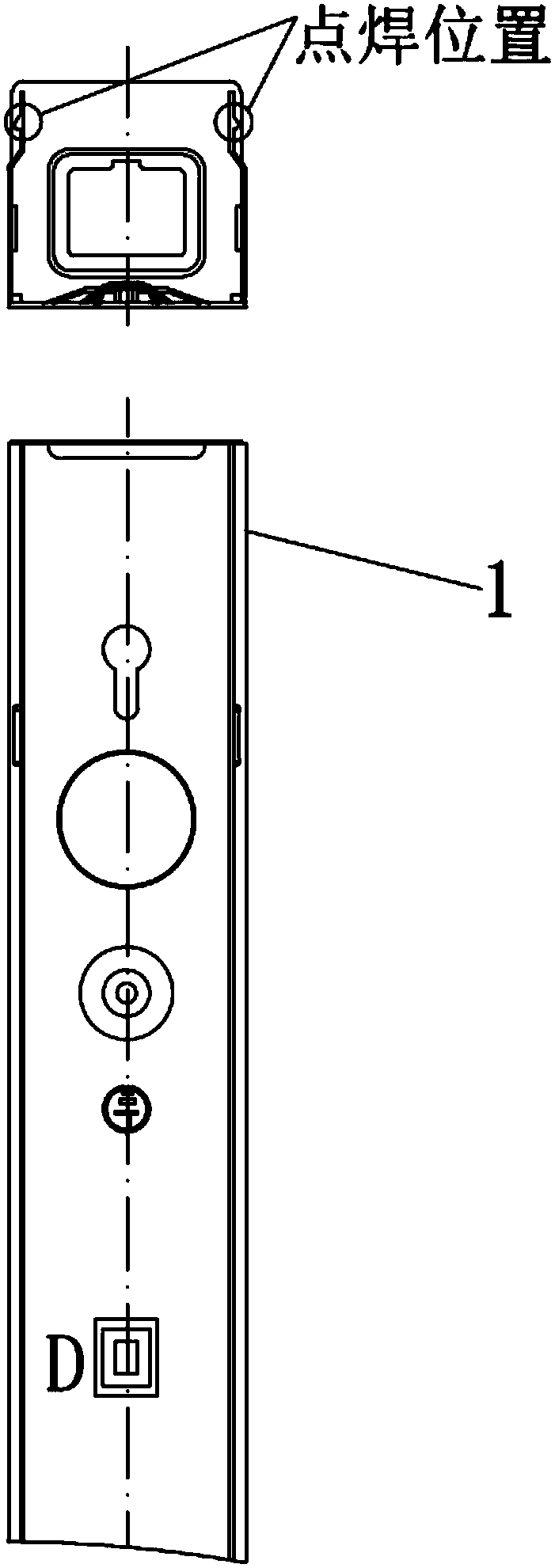
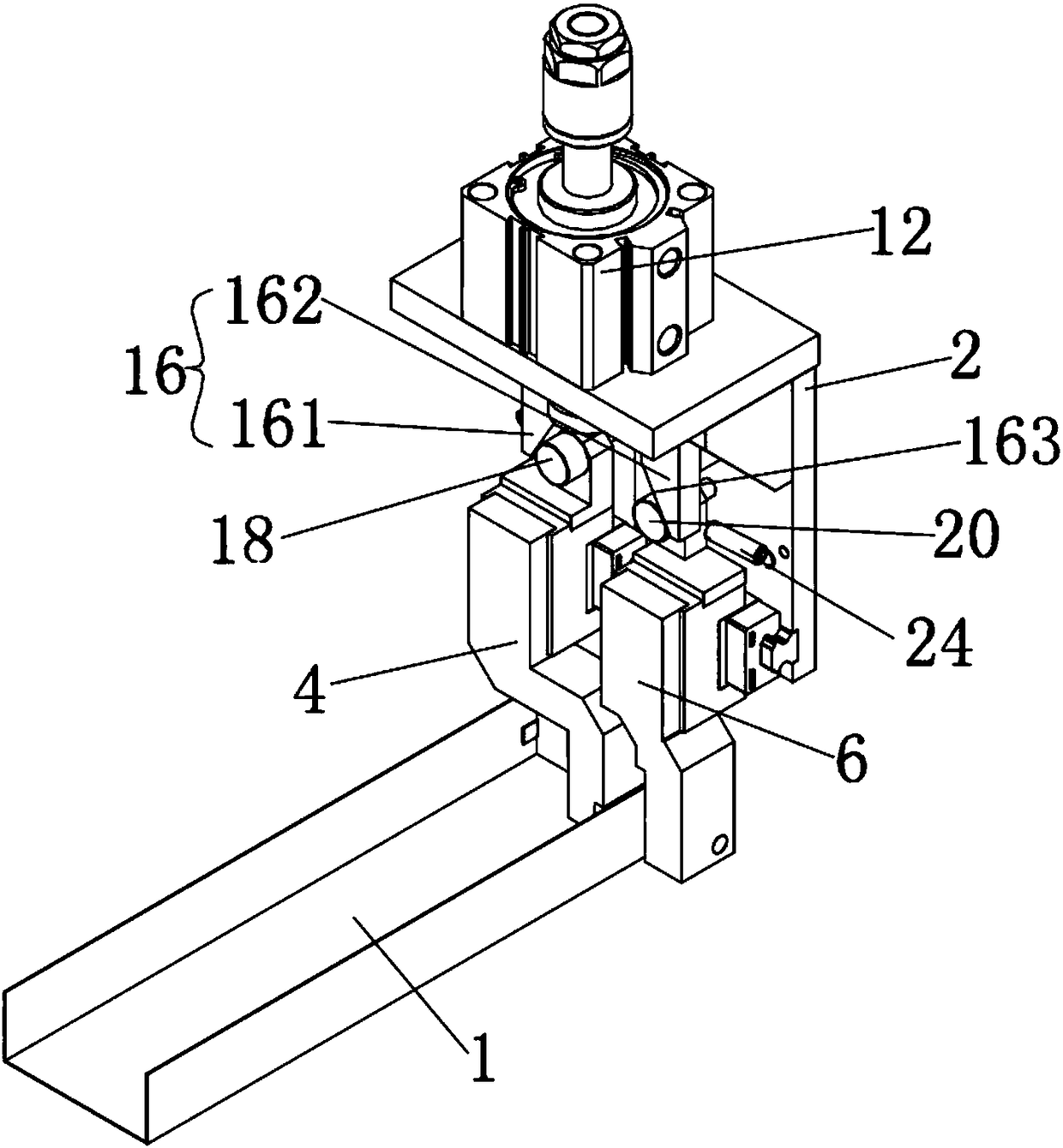
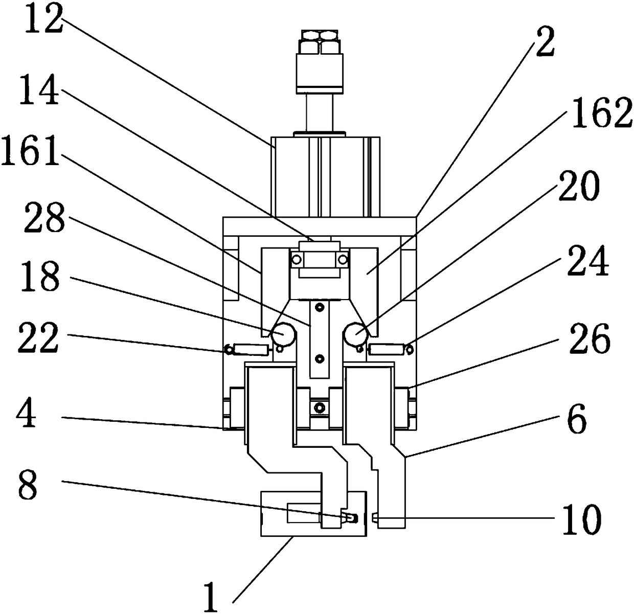
[0024] Such as Figure 2-3 As shown, this embodiment discloses a horizontal spot welding device for welding the end of a bracket lamp, including a fixing frame 2, a first electrode block 4 and a second electrode block 6 separately arranged, and the first electrode The block 4 and the second electrode block 6 are arranged on the fixed frame 2, and the first electrode block 4 and the second electrode block 6 are respectively provided with a first welding head 8 and a second welding head 10, as Figure 4 As shown, both the first electrode block 4 and the second electrode block 6 of the present invention have a shape structure matching the end of the workpiece 1 to be welded, and both the first welding head 8 and the second welding head 10 also have Matching the shape structure of the end of the workpiece 1 to be welded, the gap between the first welding head 8 and the second welding head 10 forms a space for horizontally placing the workpiece to be welded; the first electrode blo...


PUM


Abstract

The invention provides a horizontal type spot welding device for welding ends of frame lamps. The horizontal type spot welding device comprises a first electrode block and a second electrode block, which are arranged separately and vertically, wherein the first electrode block and the second electrode block are provided with a first welding head and a second welding head, respectively; a gap between the first welding head and the second welding head forms a space for horizontally placing a to-be-welded part of a workpiece; and both the first electrode block and the second electrode block can relatively move along a horizontal direction under the drive of a driving mechanism to ensure that both the first welding head and the second welding head get close to each other to perform horizontal welding on the workpiece or get far from each other to end welding. By changing a welding posture of the frame lamps, the horizontal type spot welding device provided by the invention is changed from the former side standing to the current horizontal placing, and by matching with the electrode blocks and the welding heads with optimized structural designs, the technical bottleneck that the relative distance between welding points is too short as a welding point of a frame lamp is too close to an end is solved, and automatic spot welding of the frame lamps is achieved, so that the welding quality and welding efficiency of spot welding are improved, and the labor intensity of staffs is reduced.

Description

technical field [0001] The invention belongs to the field of welding tooling technology, and relates to a spot welding device suitable for thin plate parts, in particular to a horizontal spot welding device used for welding the end of a bracket lamp. Background technique [0002] Such as figure 1 The bracket lamp shown has a special structure at the end, the welding point is too close to the end, and the relative position between the welding points is too small. The current vertical spot welding machine cannot perform automatic spot welding on it, and can only rely on manual holding. The parts are spot welded on a vertical spot welding machine; manual spot welding, spot welding positions are different, spot welding depths are different, missing welding and missing welding occur from time to time, which will inevitably affect the quality, and the welding speed of manual holding parts is slow and inefficient , the work is cumbersome and labor-intensive; with the continuous ad...

Claims


Application Information

Patent Timeline
Patent Type & Authority Patents(China)
IPC IPC(8): B23K11/11B23K11/31B23K101/18
CPCB23K11/0026B23K11/115B23K11/31B23K2101/18
Inventor 邰文涛祁灵光霰学会
Owner SUZHOU HAGONG YIKE ROBOT CO LTD
Learn More