
Laser adapter spot welding device

A spot welding device and adapter technology, applied in laser welding equipment, welding equipment, metal processing equipment, etc., can solve the problems of low production efficiency, cumbersome assembly, easy fatigue, etc., to reduce labor intensity and fatigue strength, and improve product stability. The effect of ensuring the quality of solder joints

Pending Publication Date: 2018-06-01
SHENZHEN HI OPTEL TECH
View PDF0 Cites 2 Cited by
  • Summary
  • Abstract
  • Description
  • Claims
  • Application Information

AI Technical Summary

Problems solved by technology

[0005] 1. The existing automatic assembly spot welding device cannot weld in a 45° direction, and cannot realize inclined welding with different contact areas;
[0006] 2. It is cumbersome to assemble individually and the production efficiency is low;
[0007] 3. The operator holds the assembly fixture for spot welding, the inclination angle is difficult to control, and the solder joints are unevenly distributed, which affects the stability of the optical device;
[0008] 4. Operators need to work under a microscope and are prone to fatigue

Method used


Image

  • Laser adapter spot welding device
  • Laser adapter spot welding device
  • Laser adapter spot welding device

Examples


Embodiment Construction

[0026] The present invention will be described in further detail below in conjunction with the accompanying drawings and embodiments.

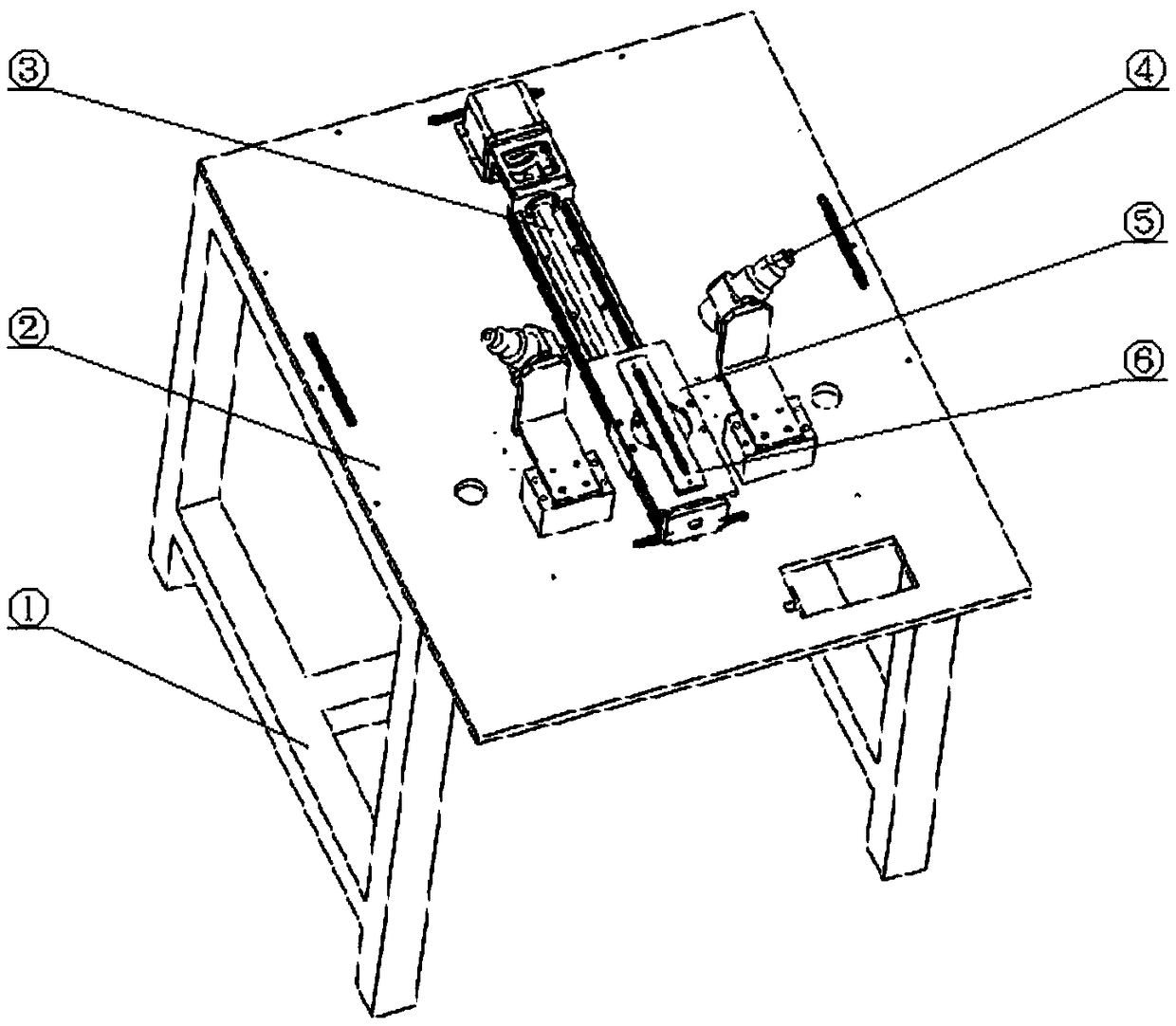
[0027] Such as image 3 As shown, the present invention includes a spot welding station, wherein the spot welding station includes a frame 1, a spot welding station base plate 2, a horizontal movement mechanism 3 arranged on the spot welding platform base plate 2, an assembly fixture 6 for installing an adapter, and a clamp fixing plate 5 and a laser welding machine 4, wherein the fixture fixing plate 5 is fixed on the horizontal moving mechanism 3 and can move horizontally under the drive of the horizontal moving mechanism 3, and the assembly fixture 6 is detachably arranged on the fixture fixing plate 5 Above, the laser welding machine 4 is fixed on the bottom plate 2 of the spot welding table to weld the adapter on the assembly fixture 6 .

[0028] The installation method of the adapter spot welding device of the laser of the present inven...


PUM


Abstract

The invention provides a laser adapter spot welding device, and belongs to the field of laser adapter assembly. The laser adapter spot welding device comprises a spot welding table, a horizontal moving mechanism arranged on the spot welding table, an assembly fixture for mounting an adapter, a fixture fixed plate and a laser welding machine, wherein the fixture fixed plate is fixed on the horizontal moving mechanism, and can be driven by the horizontal moving mechanism to horizontally move; the assembly fixture is detachably arranged on the fixture fixed plate; and the laser welding machine isfixed on the spot welding table for welding the adapter on the assembly fixture. The laser adapter spot welding device has the beneficial effects of realization of automatic spot welding, automatic control of welding point positions, fixed welding gun angles, guarantee of the welding point quality and improvement of the product stability.

Description

technical field [0001] The invention relates to the field of laser adapter assembly, in particular to a laser adapter spot welding device. Background technique [0002] Existing laser adapters include square shells and metal parts, there are figure 1 and figure 2 two structures, figure 1 The assembly and welding of the structure is completed by an automatic assembly spot welding device. The operator will assemble the metal parts to the welding fixture one by one, and then control the spot welding machine to trigger the laser automatic welding to be firm at the 0° direction of the joint between the square shell and the metal parts. [0003] figure 2 The size of the two welding surfaces of the structure is different, and the 0° direction cannot be welded firmly. figure 2 The existing assembly and fixing methods of the adapter are: ①First assemble the square shell and metal parts on the assembly fixture; ②Tighten the screws on the assembly fixture to fix the square shel...

Claims


Application Information

Patent Timeline
IPC IPC(8): B23K26/22B23K26/04B23K26/70
CPCB23K26/04B23K26/22B23K26/702
Inventor 温殷婷王硕陈雄
Owner SHENZHEN HI OPTEL TECH
Learn More