
Combined cutting tool for automatic grinding device of spotwelding electrode

A spot welding electrode and dresser technology, which is applied in the direction of manufacturing tools, grinding workpiece supports, and other manufacturing equipment/tools, can solve the problem of cutting edge wear or chipping, great difference in working load or bending moment, and cutting edge Problems such as rapid wear or chipping

Pending Publication Date: 2021-05-14
扬帆研华(天津)科技发展有限公司
View PDF0 Cites 0 Cited by
  • Summary
  • Abstract
  • Description
  • Claims
  • Application Information

AI Technical Summary

Problems solved by technology

[0006] 3. Due to the repeated positioning accuracy error of the spot welding robot, the designed working length of the cutting edge that undertakes partial grinding of the working plane of the electrode must meet the relationship greater than or equal to the sum of the working radius of the electrode to be cut and ground and the repeated positioning accuracy of the electrode, so as to ensure repeatability. Within the range of positioning accuracy, it can effectively cut and grind the part of the electrode to be repaired; from the perspective of probability and statistics, about 50% of the cutting and grinding is carried out under the condition that the local cutting edge exceeds the electrode radius. Part of the local cutting edge works under the state of hard extrusion of the reverse blade, while the cutting edge at the center of each scraping rotation of the cutting tool is to grind the working surface of the electrode under the conditions of rotating rolling and rotating tearing. It is very easy to cause rapid wear or chipping of the cutting edge in the above-mentioned area
[0007] 4. Due to the constraints of the design conditions and cutting edge working conditions mentioned in item 2, the use of cutting tools with multi-cutting edge structure for the purpose of reducing the working load of the cutting edge is limited, and the automatic breaking of the cutting edge is also excluded. The possibility of chip capacity, the so-called chip is actually a stack of chips that are continuously extruded, and the squeezed chips that are not discharged in time may hinder the continuous and stable scraping work of the cutting edge, or easily lead to accelerated wear or chipping of the cutting edge
[0009] 6. Since the axis of rotation of the cutting edge is coaxial with the axis of the electrode, during the cutting process, the difference between the rotational linear velocity and the rotational linear acceleration between the center of the cutting edge and the outer edge of the cutting edge is extremely large. The difference in working load or bending moment is very large, the outer edge of the cutting edge becomes a dangerous part due to the maximum rotational acceleration, and the cutting edge beyond the rotation axis is also another dangerous part of the cutting edge due to the hard extrusion of the reverse edge; at the same time , due to the great difference in the cutting line speed of each part of the full length of the cutting edge, it is also easy to cause the difference in the grinding quality of each part of the electrode end face after grinding
[0010] Since the edge of the cutting tool works under the above-mentioned series of extremely unfavorable working conditions, even if relatively expensive materials are selected to make the cutting tool, it is difficult to get rid of the status that the cutting tool is a frequent wearing part in the electrode automatic dresser

Method used


Image

  • Combined cutting tool for automatic grinding device of spotwelding electrode
  • Combined cutting tool for automatic grinding device of spotwelding electrode
  • Combined cutting tool for automatic grinding device of spotwelding electrode

Examples


Embodiment Construction

[0060] The technical solution of the present invention will be further described in detail below in conjunction with the accompanying drawings and specific embodiments, and the described specific embodiments are only for explaining the present invention, and are not intended to limit the present invention.

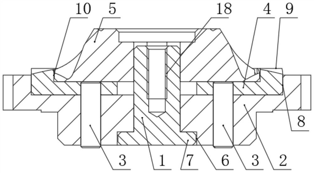
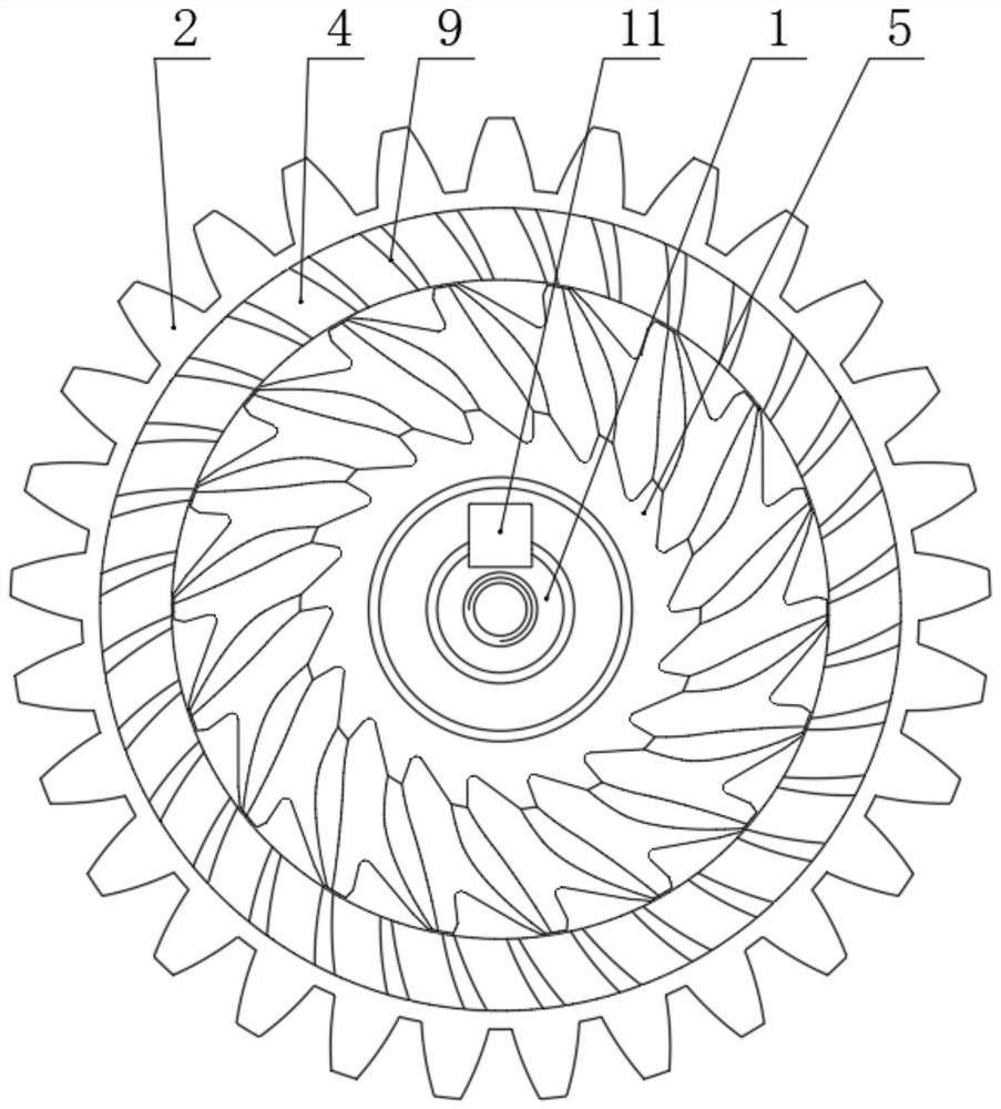
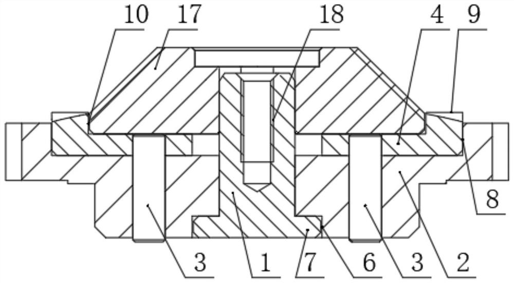
[0061] A combined cutting tool for a spot welding electrode automatic sharpener, including a cutter shaft 1, the shaft end of which is equipped with a spur gear 2; the innovation of the present invention is that: one end of the cutter shaft 1 has a flange 7, and the The inner surface of the flange 7 is used as the positioning base surface when the spur gear 2 is assembled with it; the other end of the cutter shaft 1 is provided with a threaded hole 18 in the center of the shaft, and the threaded hole 18 is used for the axial constraint of the cutter shaft 1 When the bolt assembly hole (.

[0062] Such as Picture 1-1 , Figure 1-2 , diagram 2-1 and Figure 2-2 As show...


PUM


Abstract

The invention discloses a combined cutting tool for an automatic grinding device of a spot welding electrode. The combined cutting tool comprises a cutter shaft (1), and a straight gear (2) is assembled at the shaft end of the cutter shaft (1). A flange (7) is arranged at one end of the cutter shaft (1), and the inner side surface of the flange (7) is used as a positioning base plane when the straight gear (2) and the flange (7) are combined and assembled. A threaded hole (18) is formed in the axis of the other end of the cutter shaft (1), and the threaded hole (18) is used as a bolt assembly hole when the cutter shaft (1) is axially restrained. The planeness of the working surface of the ground electrode is improved, and the beneficial effects of improving the electrode feed efficiency, guaranteeing the welding spot quality and the like are achieved.

Description

technical field [0001] The invention relates to an electrode grinding cutting tool used in resistance spot welding electrode grinding, in particular to a combined cutting tool placed in a special electrode automatic grinding device and used for grinding the working end of resistance spot welding electrodes. Background technique [0002] The electrode is placed at the end of the electrode handle, commonly known as the electrode cap. During spot welding, the flat parts of the electrode ends on both sides are the working surfaces, which hold the workpiece to be welded, and specifically implement the pressure applied to the welded part and the introduction of welding current to the workpiece to be welded. After a few points of electrode welding, due to the change of the state of the working plane of the electrode end, it needs to be ground in time. The electrode automatic grinder and the cutting tool in it are one of the methods for grinding the working end surface of the electr...

Claims


Application Information

Patent Timeline
Patent Type & Authority Applications(China)
IPC IPC(8): B24B3/00B24B41/06
CPCB24B3/00B24B41/06
Inventor 顾寅顾扬陈林刘为民吕元亮邵东辉顾啸孟少颖戴淮波李耀吴洪超
Owner 扬帆研华(天津)科技发展有限公司
Learn More