Screw assembling machine

A screw assembly machine, screw technology, applied in the direction of metal processing, metal processing equipment, manufacturing tools, etc., to achieve the effect of improving precision

Inactive Publication Date: 2017-01-04
CHONGQING TIANTENG GLASS
12 Cites 1 Cited by

AI-Extracted Technical Summary

Problems solved by technology

[0003] In view of the above deficiencies, the object of the present invention is to provide a screw assembly...

Method used

In summary, the design of the infrared locator 52 of the screw assembly machine of the present invention can improve the precision of screwing, and the aperture of the screw hole 422 of the connecting sleeve 42 can be provided with different apertures according to different types of screws The size of the outlet screw hole 422, and the diameter of the outlet screw hole 422 is 1-2 mm larger than the maximum diameter of the corresponding type of screw, and the inner wall of the outlet screw hole 422 is smoothed to ensure the smooth passage of the screw without screw jamming.
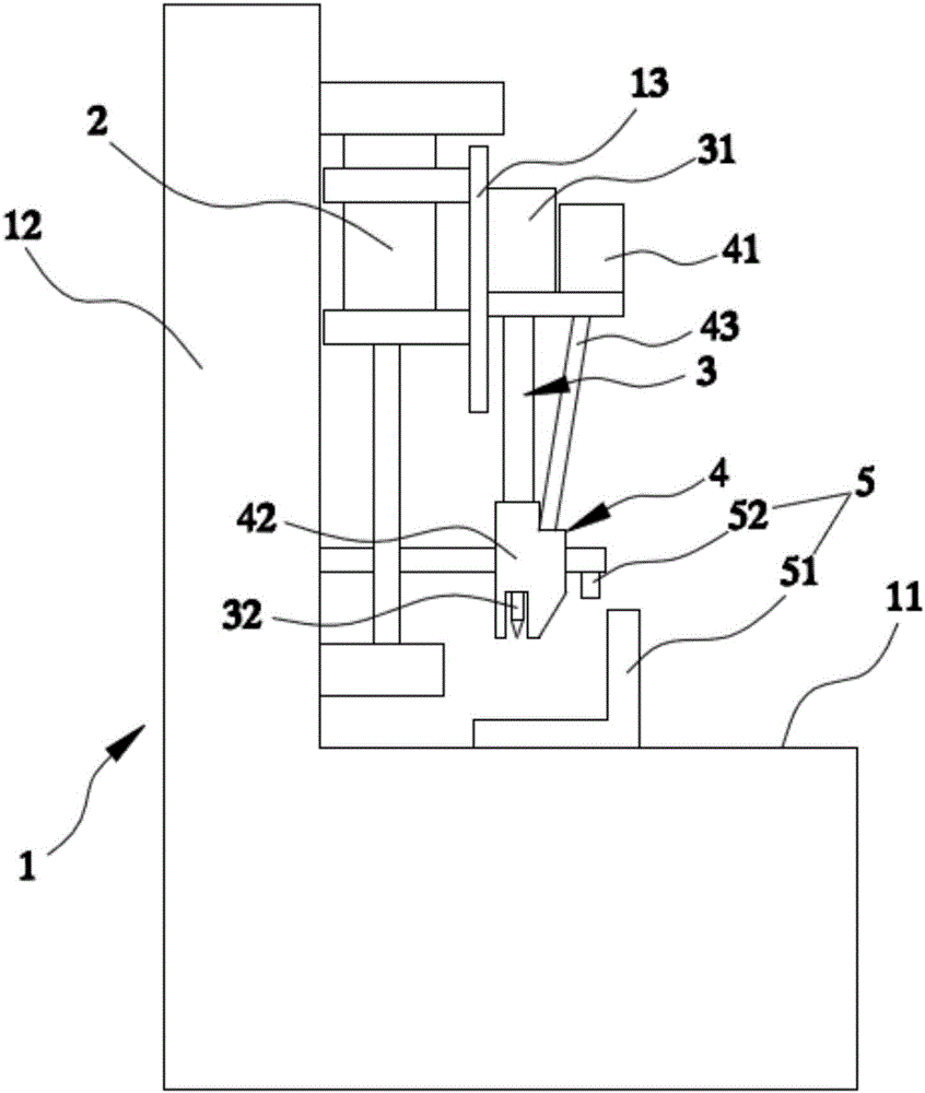
[0017] Referring to Fig. 1 and Fig. 2, a screw assembly machine includes a frame 1, a lifting cylinder 2, an electric screwdriver 3, a screw mechanism 4 and a processing positioning mechanism 5. The frame 1 is in an "L" shape, and the frame 1 includes a processing platform 11 and an installation platform 12 arranged on one side of the processing platform 11 in the vertical direction. The lifting cylinder 2 is fixedly installed on the installation platform 12, the electric screwdriver 3 and the screw mechanism 4 are fixedly installed on the lifting cylinder 2 through the fixing frame 13, ...

Abstract

The invention discloses a screw assembling machine. The screw assembling machine comprises a machine frame, a lifting cylinder, an electric screw driver, a screw outlet mechanism and a machining positioning mechanism. The machine frame comprises a machining platform and a mounting platform which is arranged on one side of the machining platform in the vertical direction; the lifting cylinder is fixedly arranged on the mounting platform. The electric screw driver and the screw outlet mechanism are fixedly arranged on the lifting cylinder through a fixed frame. The screw outlet mechanism comprises a screw storage device, a linking jacket and a connecting sleeve which is arranged between the screw outlet mechanism and the linking jacket; a through hole is vertically formed in the linking jacket in a penetrating manner, and a screw outlet hole of which the upper end and the lower end are respectively communicated with the connecting sleeve and the through hole is formed in one side of the linking jacket in the penetrating manner; the linking jacket is arranged outside the lower end of the electric screw driver in a sleeving manner. The machining positioning mechanism comprises a positioning right-angle plate which is arranged on the machining platform and an infrared positioning device which is arranged on one side of the electric screw driver and can be projected to the positioning right-angle plate. The screw assembling machine has the advantages that the screw assembling precision is high and the situation that a screw is clamped is avoided.

Application Domain

Metal working apparatus

Technology Topic

Fixed frameEngineering

Image

  • Screw assembling machine
  • Screw assembling machine

Examples

  • Experimental program(1)

Example Embodiment

[0015] In order to describe in detail the technical content, structural features, achieved objectives and effects of the present invention, the following is a detailed description in conjunction with the embodiments and accompanying drawings.
[0016] The technical solutions of the present invention will be clearly and completely described below in conjunction with the accompanying drawings. Obviously, the described embodiments are part of the embodiments of the present invention, rather than all of them. Based on the embodiments of the present invention, all other embodiments obtained by those of ordinary skill in the art without creative work shall fall within the protection scope of the present invention. In the description of the present invention, it should be noted that the terms "center", "upper", "lower", "left", "right", "vertical", "horizontal", "inner", "outer", etc. The indicated orientation or positional relationship is based on the orientation or positional relationship shown in the drawings, and is only for the convenience of describing the present invention and simplifying the description, rather than indicating or implying that the pointed device or element must have a specific orientation or a specific orientation. The structure and operation cannot therefore be understood as a limitation of the present invention.
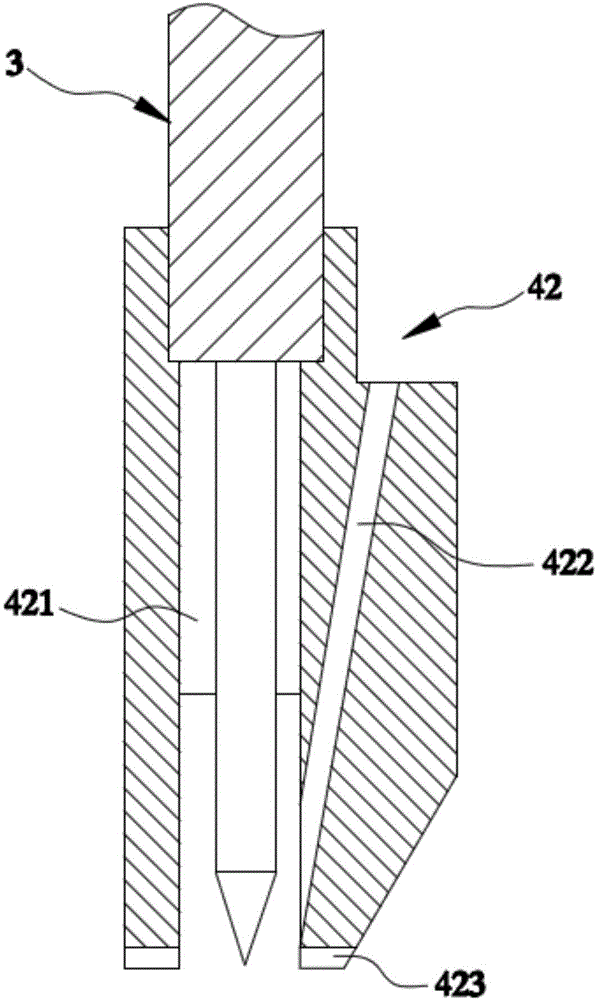
[0017] See figure 1 with figure 2 , A screw assembly machine, including a frame 1, a lifting cylinder 2, an electric screwdriver 3, a screw-out mechanism 4, and a processing positioning mechanism 5. The frame 1 has an "L"-shaped structure. The frame 1 includes a processing platform 11 and an installation platform 12 vertically arranged on one side of the processing platform 11. The lifting cylinder 2 is fixedly installed on the installation platform 12, and the electric screwdriver 3 and the screw-out mechanism 4 are fixedly installed on the lifting cylinder 2 through a fixing frame 13, and can be moved up and down by the lifting cylinder 2, The lower end of the electric screwdriver 3 has magnetism, which can effectively adsorb the screw head when the screw is discharged, thereby completing subsequent processing. The screw out mechanism 4 includes a screw storage device 41, an adapter sleeve 42, and a connecting sleeve 43 arranged between the screw storage device 41 and the adapter sleeve 42. The adapter sleeve 42 is provided with a through hole 421 up and down. One side of the adapter sleeve 42 is provided with an outlet screw hole 422 whose upper and lower ends are respectively communicated with the connecting sleeve 43 and the through hole 421. The outlet of the lower end of the screw hole 422 is adjacent to the lower end of the electric screwdriver 3. The connecting sleeve 42 is sleeved on the outer side of the lower end of the electric screwdriver 3. The processing positioning mechanism 5 includes a positioning right angle plate 51 arranged on the processing platform 11 and an infrared locator 52 which is arranged on the side of the electric screwdriver 3 and can be projected on the positioning right angle plate 51 to improve the accuracy of screwing.
[0018] The aperture of the screw hole 422 of the adapter sleeve 42 can be set according to different types of screws with different aperture sizes, and the aperture of the screw hole 422 is larger than the maximum diameter of the corresponding model screw by 1 to 2 mm, and the screw hole The inner wall of 422 is smoothed to ensure the smooth passage of the screws without screw jamming.
[0019] The electric screwdriver 3 includes a micromotor 31 and a screwdriver 32 installed on the micromotor 31, and the micromotor 31 is fixedly installed on the fixing frame 13.
[0020] In this embodiment, the lower end of the adapter sleeve 42 is provided with a protective layer 423, which can prevent the adapter sleeve 42 from crushing the product after the screw is installed.
[0021] In summary, the design of the infrared locator 52 of the screw assembly machine of the present invention can improve the accuracy of screwing, and the aperture of the screw hole 422 of the adapter sleeve 42 can be set to different aperture sizes according to different types of screws. The screw hole 422 is out, and the hole diameter of the screw hole 422 is larger than the maximum diameter of the corresponding model screw by 1 to 2 mm, and the inner wall of the screw hole 422 is smoothed to ensure the smooth passage of the screw without screw jamming.
[0022] Based on the disclosure and teaching of the foregoing specification, those skilled in the art of the present invention can also make changes and modifications to the foregoing embodiments. Therefore, the present invention is not limited to the specific embodiments disclosed and described above, and some modifications and changes to the present invention should also fall within the protection scope of the claims of the present invention. In addition, although some specific terms are used in this specification, these terms are only for convenience of description and do not constitute any limitation to the present invention. Other devices that are the same or similar to them are all within the protection scope of the present invention.

PUM

no PUM

Description & Claims & Application Information

We can also present the details of the Description, Claims and Application information to help users get a comprehensive understanding of the technical details of the patent, such as background art, summary of invention, brief description of drawings, description of embodiments, and other original content. On the other hand, users can also determine the specific scope of protection of the technology through the list of claims; as well as understand the changes in the life cycle of the technology with the presentation of the patent timeline. Login to view more.

Similar technology patents

Clock hand-off circuit

ActiveUS20110128052A1high precision
Owner:ADVANTEST CORP

Classification and recommendation of technical efficacy words

  • High precision

Method for forecasting short-term power in wind power station

InactiveCN102102626AHigh precision
Owner:NORTH CHINA ELECTRIC POWER UNIV (BAODING) +1

Numerical control machine tool wear monitoring method

InactiveCN102091972AHigh precisionReal-time monitoring of tool wear
Owner:HUAZHONG UNIV OF SCI & TECH +1

Advertisement recommendation method and apparatus

ActiveCN104965890AHigh precisionPrecise screening
Owner:SHENZHEN TENCENT COMP SYST CO LTD
Why Eureka
Try Eureka