Supercharge Your Innovation With Domain-Expert AI Agents!

Equipment for automatic station switching during pipe fitting processing

A technology for automatic switching and pipe fittings, which is applied in the direction of metal processing equipment, metal processing, metal processing machinery parts, etc., can solve the problems of reducing the degree of automation of pipe fittings and increasing labor costs

Active Publication Date: 2018-02-06
徐州天骋智能科技有限公司
View PDF6 Cites 0 Cited by
  • Summary
  • Abstract
  • Description
  • Claims
  • Application Information

AI Technical Summary

Problems solved by technology

In the prior art, the switching between the two stations after end milling and shot blasting is often done manually, which greatly reduces the degree of automation in pipe fitting processing and increases labor costs

Method used


Image

  • Equipment for automatic station switching during pipe fitting processing
  • Equipment for automatic station switching during pipe fitting processing
  • Equipment for automatic station switching during pipe fitting processing

Examples


Embodiment Construction

[0020] The present invention will be further described below in conjunction with the accompanying drawings and specific embodiments.

[0021] Working principle of the present invention:

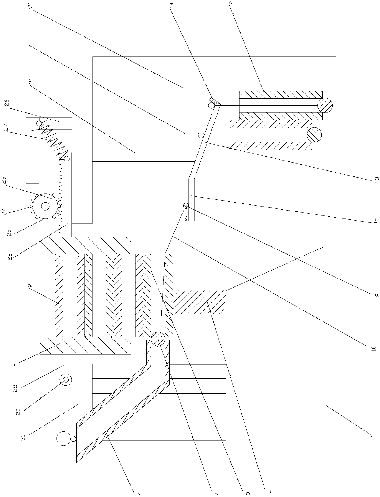
[0022] First, the pipe fittings that have just milled the end face are placed in the barrel, the pipe fittings are in a horizontal state, the lowest pipe fitting is against the support block, and the lowest pipe fitting is separated from the lower port of the barrel, as shown figure 1 As shown; the operator puts a group of steel ball pulling mechanisms into the inclined tube, and the small steel ball is located below the large steel ball, that is, to ensure that the small steel ball enters the inclined tube first; the small steel ball and the large steel ball roll along the inner wall of the inclined tube, and the small steel ball takes the lead. Through the through hole on the pipe fitting, after the small steel ball leaves the through hole of the pipe fitting, it makes a parabolic motion an...


PUM


Abstract

The invention discloses automatic station switching equipment used in the pipe machining process. The equipment comprises a workbench (1). A charging barrel (3) used for containing pipes (2) is arranged on the workbench (1). A linear rack (22) is arranged on the side wall of the charging barrel (3) and slidably connected to the workbench (1) through a dovetail groove. A gear (23) used for being in engaging transmission with the linear rack (22) is rotatably connected to the workbench (1). The gear (23) comprises a toothed zone (24) used for being in engaging transmission with the linear rack (22), and a toothless zone (25) used for being separated from the linear rack (22). The automatic station switching equipment used in the pipe machining process is high in automation degree and lower in manual cost.

Description

technical field [0001] The invention relates to the technical field of station switching during pipe fitting processing, in particular to a device for automatic station switching during pipe fitting processing. Background technique [0002] During the processing of pipe fittings, in order to meet the technical requirements of pipe fittings, it is usually necessary to mill the end faces of both ends of the pipe fittings to ensure that the accuracy of the two ends of the faces meets the work requirements. In addition, after milling the end faces of both ends of the pipe fittings, it is also necessary to perform shot blasting on the outer peripheral wall of the pipe fittings. In the prior art, the switching between the two stations after end milling and shot blasting is often done manually, which greatly reduces the degree of automation in pipe fitting processing and increases labor costs. Contents of the invention [0003] The technical problem to be solved by the present i...

Claims


Application Information

Patent Timeline
Patent Type & Authority Patents(China)
IPC IPC(8): B23Q7/00B23Q1/26
CPCB23Q1/26B23Q7/00
Inventor 王奇峰许海波
Owner 徐州天骋智能科技有限公司
Features
  • R&D
  • Intellectual Property
  • Life Sciences
  • Materials
  • Tech Scout
  • Unparalleled Data Quality
  • Higher Quality Content
  • 60% Fewer Hallucinations
Learn More