Bearing puller

A puller, axial technology, applied in the field of bearing puller devices, capable of tackling surfaces, either pulling outwards on rolling elements, cages or even outer rings of bearings, sliding, or scratching inwards for assembly Axis, unstable moving state and other problems, to achieve the effect of reliable positioning, fast location finding, and convenient disassembly operation

Inactive Publication Date: 2017-01-04
AB SKF
View PDF8 Cites 9 Cited by
  • Summary
  • Abstract
  • Description
  • Claims
  • Application Information

AI Technical Summary

Problems solved by technology

Obviously, this process is quite time-consuming and inconvenient to use the nut adjustment
To make matters worse, when using nut positioning, the nut positioning can only limit the movement of the drawing block from one side
If the drawing block is not really close to the nut, it is actually in an unstable active state during the drawing process, and it is easy to slide in any direction along the threaded rod, either scratching the surface of the assembly shaft inward, or pulling it outward Buckled on the rolling element, cage or even the outer ring of the bearing, resulting in accidents

Method used


Image

  • Bearing puller
  • Bearing puller
  • Bearing puller

Examples


Embodiment Construction

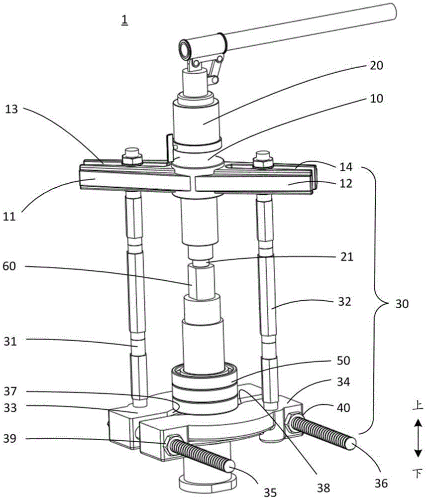
[0016] The puller provided by the present invention is generally consistent with the traditional puller in terms of overall structure, the only difference is that the pair of pulling blocks use the positioning mode of "slider + positioning member" to replace the "thread" described in the background technology. Rod + Locating Nut" positioning mode.

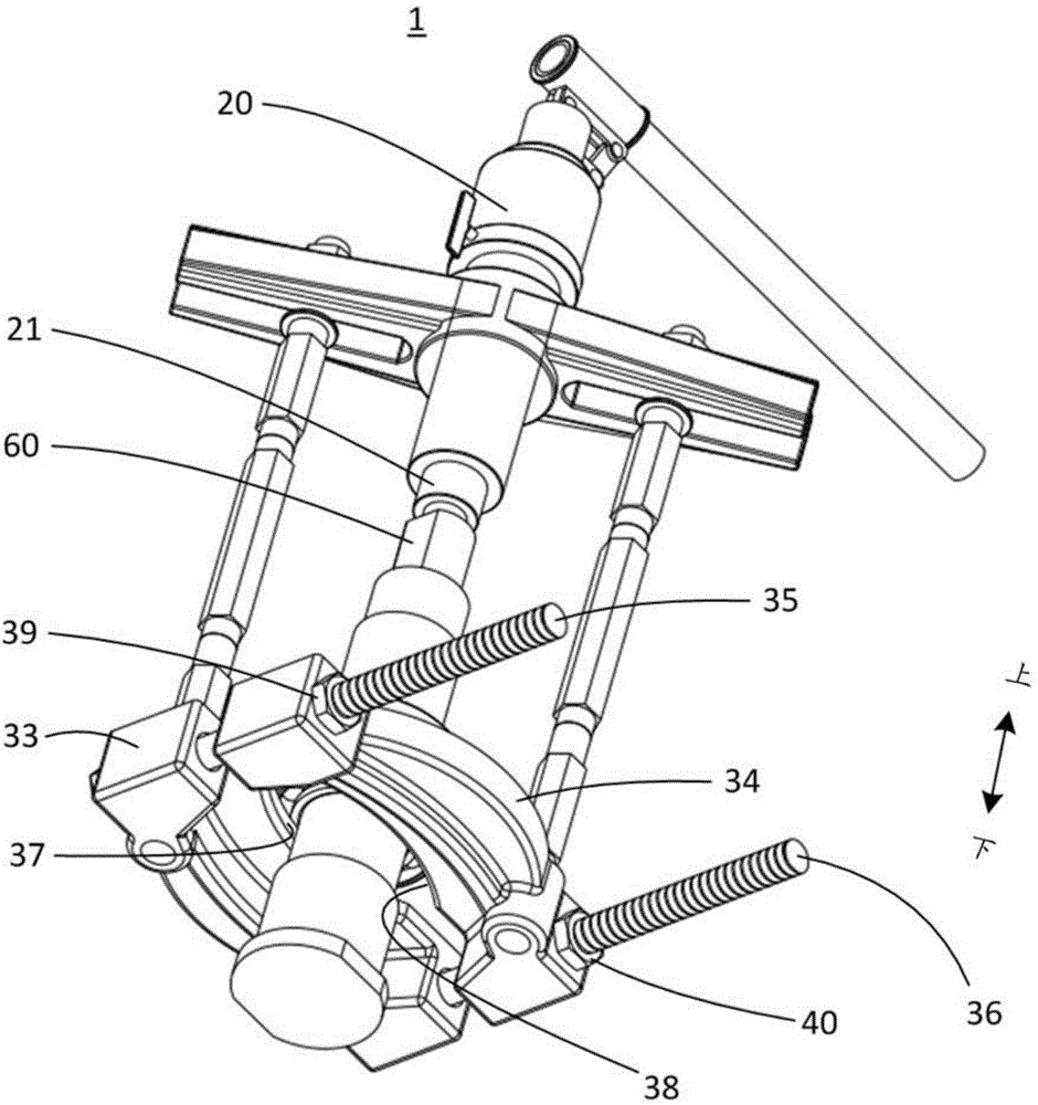
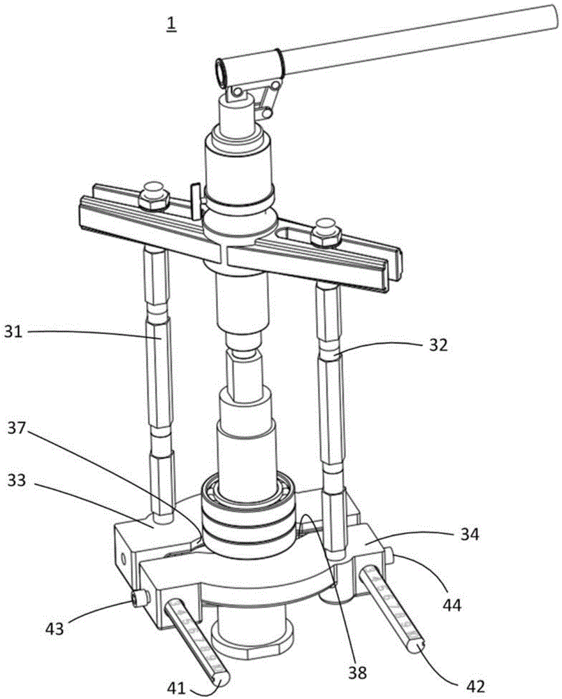
[0017] Specifically, as image 3 and 4 As shown, the pulling blocks 33 and 34 positioned at the longitudinal ends of the gripping arms 31 and 32 are arranged side by side on a pair of parallel sliding bars 41 and 42, and are arranged on a pair of sliding bars in a series connection similar to train carriages. 41 and 42 on the guide rail. By adjusting the relative distance between the drawing blocks 33 and 34 on the slide bars 41 and 42 , the size of the opening between the opposing lips 37 and 38 of a pair of drawing blocks can be smoothly adjusted.

[0018] exist image 3 and 4 In the specific embodiment shown, the drawing bl...


PUM


Abstract

A puller device which is used for detaching an annular component from an assembling shaft thereof comprises a supporting platform, a maintaining mechanism and a driving mechanism. The supporting platform is used for bearing internal stress generated by the puller device in an operation process. The maintaining mechanism is supported by the supporting platform and is used for preventing the annular component from moving in the axial direction in a detaching process. A pair of pulling blocks is arranged at the tail end of the maintaining mechanism in the longitudinal direction, can surround the assembling shaft to form a pair of lips of which the radial sizes correspond to the radial size of the annular component after being folded, and is used for fastening an end surface of one side of the annular component in a detaching process to prevent the annular component to move along the assembling shaft in the axial direction in a detaching process. The driving mechanism is supported by the supporting platform, and is used for applying a separation acting force to the assembling shaft in a detaching process to force the assembling shaft to be separated from the annular component in the axial direction. The lips of the pair of pulling blocks are opposite, and are arranged on a pair of parallel sliding rods in parallel in a striding manner. At least one pulling block can move along the pair of sliding rods so as to adjust the distance between the pulling block and the other pulling block, and the pulling block can be positioned on the pair of sliding rods in a lockable mode through a positioning component.

Description

technical field [0001] The present invention relates to a bearing puller apparatus capable of detaching an annular member such as a bearing from its assembly shaft. Background technique [0002] Bearing pullers can disassemble bearings and other annular components from mounting shafts, and thus are widely used in the field of bearings. exist figure 1 In the shown perspective view, the puller 1 as a whole includes: a support platform (support platform) 10 that is sufficient to withstand the internal force of the system generated during pulling; Actuator means 20 for the driving force required to break free from the tightening action of the bearing 50; and a holder means 30 for ensuring that the bearing 50 remains axially positioned relative to the support platform 10 when drawing. [0003] Existing bearing pullers are formed in various shapes and structures according to their purposes. figure 1 The puller shown in is a puller mainly used for removing the bearing on the mac...

Claims


Application Information

Patent Timeline
Patent Type & Authority Applications(China)
IPC IPC(8): B25B27/073
CPCB25B27/062B25B27/064
Inventor 毛华伟D.乔达纳
Owner AB SKF
Why Eureka
Try Eureka