Equipment capable of punching ceiling and mounting expansion bolt conveniently

A technology for expansion bolts and ceilings, applied in metal processing equipment, metal processing, manufacturing tools, etc., can solve problems such as unfavorable construction personnel's personal health, access to construction personnel, frequent lifting, movement and alignment.

Pending Publication Date: 2018-04-20
SHENZHEN STYLE DECORATION
View PDF0 Cites 13 Cited by
  • Summary
  • Abstract
  • Description
  • Claims
  • Application Information

AI Technical Summary

Problems solved by technology

[0003] Since the ceiling is relatively high from the ground, generally 3 to 5 meters, it is necessary to climb a height, and when the percussion drill excavates blind holes, the impact force is relatively large, and the construction workers are easy to fall from a high place, causing safety accidents; and, due to the construction The personnel position is directly below the pre-opened blind hole. The construction personnel need to align with the pre-drilled hole position during construction. In this way, when the percussion drill opens the blind hole on the ceiling, the concrete slag and dust will directly fall on the construction personnel, and the concrete slag and The dust will scatter to the hair, clothes and skin surface of the construction workers, enter the respiratory tract of the construction workers, and easily confuse the eyes of the construction workers, which is not conducive to the personal health of the construction workers
[0004] When the existing equipment for drilling holes on the ceiling and installing expansion bolts is used, the equipment is generally raised to a predetermined height through the lifting device on the equipment; then, the mobile equipment is used to align the drill bit of the drilling device The position of the hole; then, dig a blind hole on the ceiling; then, lower the height of the equipment through the lifting device; then, remove the drill bit on the drilling device (the purpose of removing the drill bit is: to avoid when installing the assembly Interference between the assembly and the drill bit, that is, when the drill bit and the assembly rises with the lifting device, the drill bit will affect the smooth penetration of the assembly into the ceiling after the drill bit touches the ceiling), and at the same time put the assembly on the expansion bolt installation device; then, Use the lifting device to raise the equipment to the preset height again; then, move the equipment to align the assembly with the blind hole pre-opened by the drilling device; then, use the lifting device to drive the assembly into the blind hole, and finally , the lifting device descends to separate the equipment from the assembly; only one assembly can be loaded into the expansion bolt installation device of the existing equipment for drilling holes in the ceiling and installing expansion bolts, and each time the assembly is driven into It is necessary to move the equipment to find and align the position of the blind hole, so the existing equipment for drilling holes in the ceiling and installing expansion bolts needs to be frequently lifted, moved and aligned during construction, which is complex and inefficient.

Method used


Image

  • Equipment capable of punching ceiling and mounting expansion bolt conveniently
  • Equipment capable of punching ceiling and mounting expansion bolt conveniently
  • Equipment capable of punching ceiling and mounting expansion bolt conveniently

Examples


Embodiment Construction

[0036] The following will clearly and completely describe the technical solutions in the embodiments of the present invention with reference to the drawings in the embodiments of the present invention.

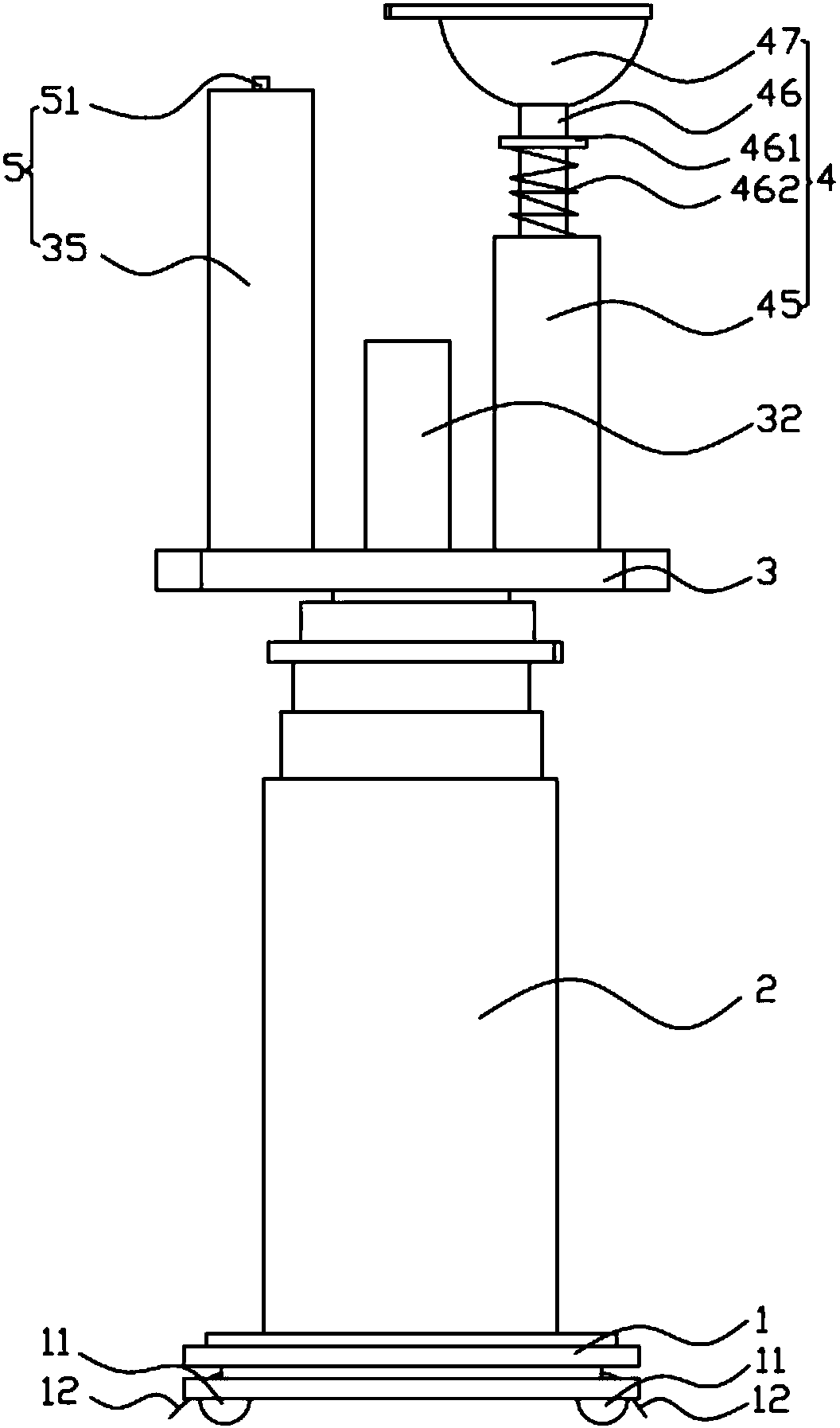
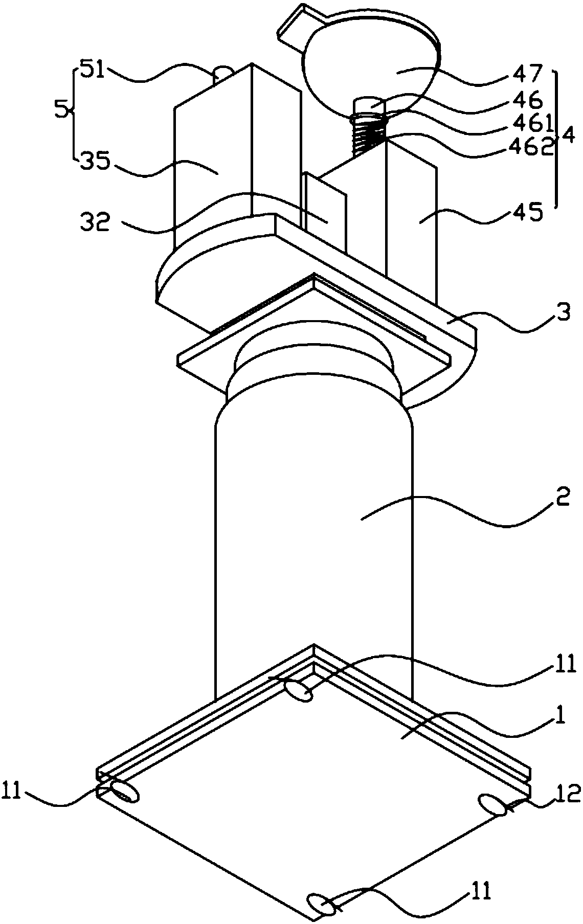
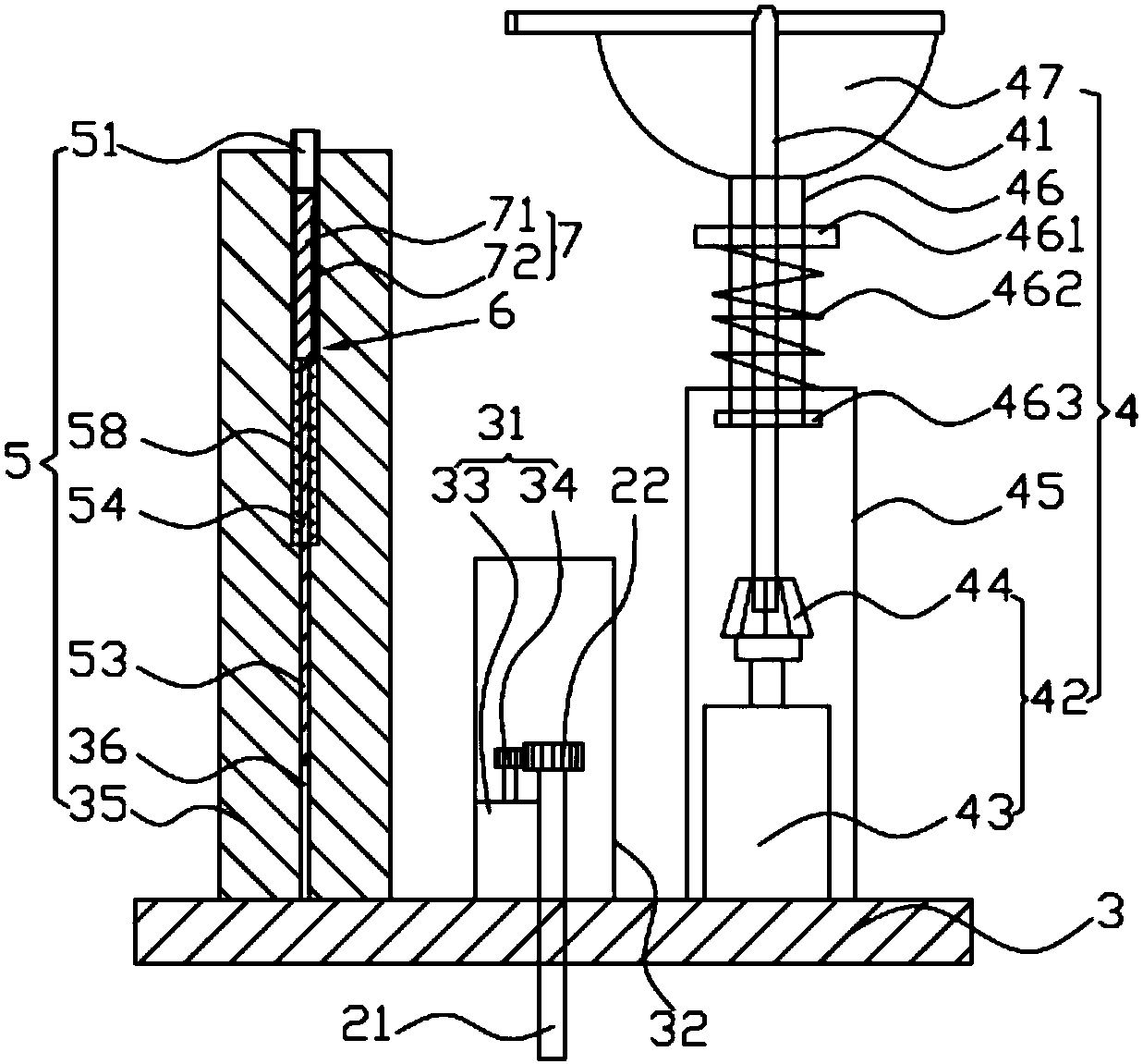
[0037] Such as Figure 1~4 As shown, the device provided by the embodiment of the present invention is convenient for punching holes in the ceiling and installing expansion bolts. It includes a base 1 on which a vertical lifting device 2 is fixed. The rotating platform 3 is provided, and the two sides of the upper part of the rotating platform 3 are respectively fixed with a drilling device 4 and an expansion bolt installation device 5, and the expansion bolt installation device 5 is inserted with a clip-type feeding device 6;

[0038] The base 1 is placed on the ground;

[0039] The lifting device 2 is used to drive the rotating platform 3 to move up and down, thereby driving the drilling device 4 and the expansion bolt installation device 5 to move up and down;

[0040] Th...


PUM


Abstract

A device that is convenient for drilling holes in the ceiling and installing expansion bolts, including a base, on which a lifting device is fixed, the top of the lifting device is rotatably connected to a rotating platform, and both sides of the upper part of the rotating platform are respectively fixed with drilling devices and expansion bolts Installation device, the expansion bolt installation device is plugged with a clip-type feeding device; the base is placed on the ground; the lifting device is used to drive the rotating platform to move up and down; the rotating platform is driven by the first driving device to rotate; the drilling device includes a drill bit; The bolt installation device includes a conduit. The upper end of the conduit is lower than the upper end of the drill bit. The inner hole of the conduit only allows an assembly formed by a countersunk bolt and an expansion tube to pass through. The conduit and the drill bit are symmetrically arranged on both sides of the rotating platform, and a roof is fixed below the conduit. The output device; the clip-type feeding device has multiple assemblies built in, and the clip-type feeding device is used to sequentially transport multiple assemblies between the conduit and the ejector device. The operation of the equipment is simple, efficient and safe.

Description

technical field [0001] The invention belongs to the technical field of interior decoration, and in particular relates to a device for punching holes in the ceiling and installing expansion bolts. Background technique [0002] When decorating the indoor ceiling, it is first necessary to use a percussion drill to dig a blind hole on the ceiling, and then drive the expansion bolt into the pre-excavated blind hole; the expansion bolt mainly includes countersunk bolts, expansion tubes, flat washers, spring pads and hexagonal nuts, the upper end of the countersunk head bolt is inverted tapered, and the outer peripheral wall of the lower end of the countersunk head bolt is fixed with an external thread for screwing with the hexagonal nut, and the expansion tube, flat washer and spring washer are set sequentially from top to bottom On the outer peripheral wall of the countersunk bolt, the upper end of the expansion tube is provided with a number of vertical cutouts, and the hexagona...

Claims


Application Information

Patent Timeline
Patent Type & Authority Applications(China)
IPC IPC(8): B23P19/06B28D1/14
CPCB28D1/14B23P19/06B28D1/146
Inventor 曲胜李小军徐家辉黄斌
Owner SHENZHEN STYLE DECORATION
Why Eureka
Try Eureka