Cement mixer

A technology for cement mixers and mixing barrels, applied in cement mixing devices, control devices, clay preparation devices, etc., can solve the problems of large mixers, insufficient size, and wear on the bottom surface, and achieve good cleaning effects, convenient movement, and reduced noise. Effect

Inactive Publication Date: 2017-01-04
苏州旋特自动化科技有限公司
View PDF0 Cites 2 Cited by
  • Summary
  • Abstract
  • Description
  • Claims
  • Application Information

AI Technical Summary

Problems solved by technology

[0002] Cement is a commonly used leader material. It usually needs to be fully mixed with sand, water and other additives before use. The general mixing devices are mixer trucks and large and medium-sized mixers, which are suitable for large and medium-sized projects. At present, cement mixers have been used in various In the field of construction, the current mixer is relatively large in size. When working in a small space, it does not need a lot of concrete materials, and there is not enough space for large and medium-sized machinery. When mixing, it is easy to splash materials during high-speed mixing, which is harmful to the environment. Causes pollution and also vibrates when mixing, which not only creates a lot of noise, but also causes wear on the bottom surface, and the life of the fleet mixer

Method used


Image

  • Cement mixer

Examples


Embodiment Construction

[0012] The following will clearly and completely describe the technical solutions in the embodiments of the present invention with reference to the accompanying drawings in the embodiments of the present invention. Obviously, the described embodiments are only some, not all, embodiments of the present invention. Based on the embodiments of the present invention, all other embodiments obtained by persons of ordinary skill in the art without making creative efforts belong to the protection scope of the present invention.

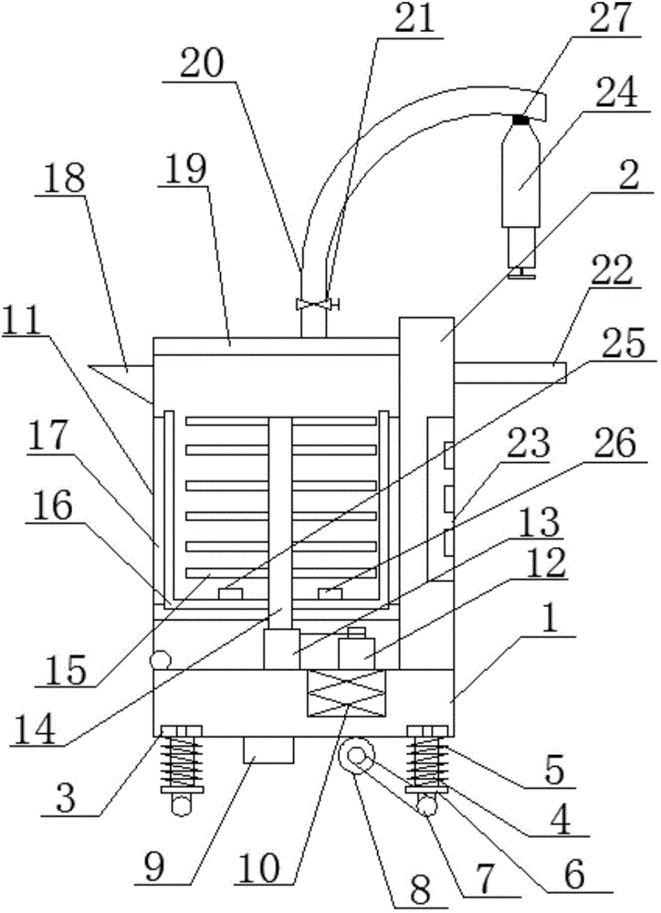
[0013] see figure 1 , in an embodiment of the present invention, a cement mixer includes a base 1 and a mixing bucket 11, the underside of the base 1 is connected with a support column 4 through a nut 3, and a spring 5 is sleeved on the support column 4, and the support column The lower end of 4 is provided with limit plate 6, and the upper end of described spring 5 is connected with base 1, and the lower end of spring 4 is connected with limit plate 6, utiliz...


PUM


Abstract

The invention discloses a cement mixer. The cement mixer comprises a base and a stirring barrel; the lower side of the base is connected with support columns through nuts; each support column is sleeved with a spring; a limiting plate is arranged at the lower end of each support column; universal wheels are arranged at the lower ends of the limiting plates; an accumulator and a motor are arranged at the lower end of the base; the left lower end of the stirring barrel and the left upper end of the base are connected through a rotating shaft; a support device is arranged on the upper side of the base; a driving motor and a reduction gearbox are arranged at the bottom of the stirring barrel; a U-shaped stirring piece is arranged at the lower part of the stirring shaft; scrapers are arranged on the left and right sides of the U-shaped stirring piece; a temperature inductor and a viscosity inductor are respectively arranged at the left and right ends of the upper side of the U-shaped stirring piece; a barrel cover is arranged at the upper end of the stirring barrel; a discharge port is formed in the upper part of the left side of the stirring barrel; a water inlet pipe is arranged in the middle of the upper side of the barrel cover; an air nozzle is arranged at one end, far from the barrel cover, of the water inlet pipe; and the air nozzle is detachably connected with an air cylinder. The cement mixer is simple in structure, is convenient to use, saves both time and labors, is excellent in vibration reducing effect, and is long in service life.

Description

technical field [0001] The invention relates to the field of cement mixing equipment, in particular to a cement mixer. Background technique [0002] Cement is a commonly used leader material. It usually needs to be fully mixed with sand, water and other additives before use. The general mixing devices are mixer trucks and large and medium-sized mixers, which are suitable for large and medium-sized projects. At present, cement mixers have been used in various In the field of construction, the current mixer is relatively large in size. When working in a small space, it does not need a lot of concrete materials, and there is not enough space for large and medium-sized machinery. When mixing, it is easy to splash materials during high-speed mixing, which is harmful to the environment. Causes pollution, and it vibrates when mixing, which not only creates a lot of noise, but also causes wear and tear on the bottom surface, and the life of the fleet mixer. Contents of the inventi...

Claims


Application Information

Patent Timeline
Patent Type & Authority Applications(China)
IPC IPC(8): B28C5/16B28C5/08B28C7/02
CPCB28C5/161B28C5/0806B28C5/0812B28C5/0856B28C7/024
Inventor 梁昀翔
Owner 苏州旋特自动化科技有限公司
Why Eureka
Try Eureka