Die for producing computer display screen base and guide structure thereof

A guide structure and mold technology, applied in the field of molds, can solve problems such as jamming, limited service life and effect of guide posts and guide sleeves, long friction between guide posts and guide sleeves, etc. The effect of reducing the amount of heat generation and wear

Inactive Publication Date: 2017-01-04
FUZHOU JUANG PRECISION MOLD TECH
View PDF6 Cites 2 Cited by
  • Summary
  • Abstract
  • Description
  • Claims
  • Application Information

AI Technical Summary

Problems solved by technology

[0004] However, the sliding of the guide post in the guide sleeve often causes stuck problems due to the fast mold opening and closing speed and the long friction between the guide post and the guide sleeve. Since the end of the guide post needs to be in the guide sleeve all the time, the guide post The friction stroke at the end is the opening and closing stroke of the mold. In the prior art, this design cannot be avoided, that is, the friction stroke at the end of the guide post cannot be changed, resulting in the service life and effect of the guide post and the guide sleeve being affected. largely restricted

Method used


Image

  • Die for producing computer display screen base and guide structure thereof
  • Die for producing computer display screen base and guide structure thereof
  • Die for producing computer display screen base and guide structure thereof

Examples


Embodiment 1

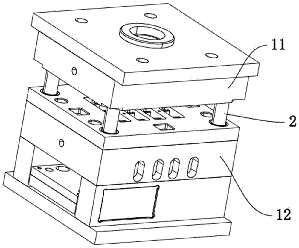
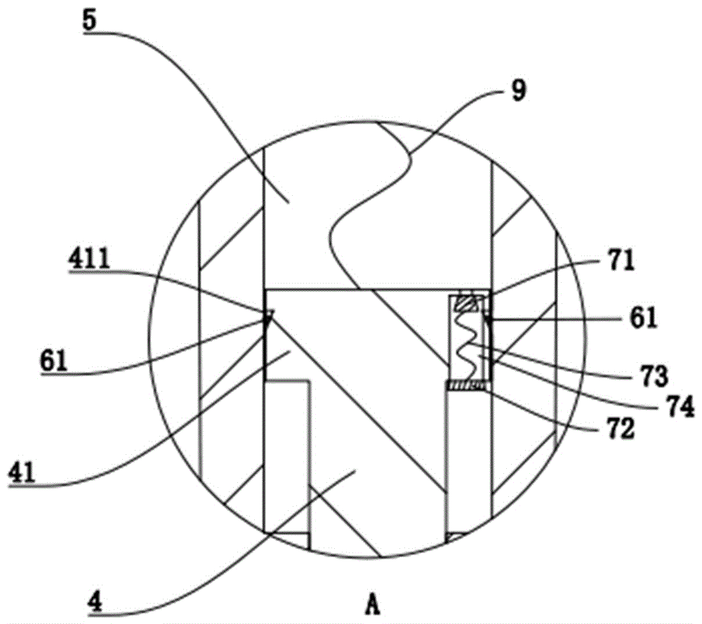
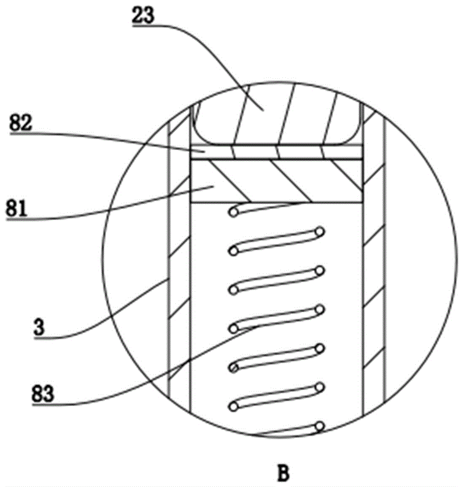
[0037] Embodiment 1, a kind of mold that is used to produce computer display screen base and its guiding structure, refer to the attached figure 1 , is the state diagram of the mold when the mold is opened. At this time, the cooperation between the guide post 2 and the guide sleeve 3 is in the figure 2 status, please refer to the attached image 3 , guide column 2 is divided into fixed column 21 fixed with movable mold 12 here, a second movable column 22 and first movable column 23, between second movable column 22 and fixed column 21, first movable column 23 and The connection between the second movable columns 22 is realized through the interspersed column 4 and the sliding chamber 5 , and the end of the intersecting column 4 is provided with a sliding block 41 which is slidably connected with the sliding chamber 5 .

[0038] A one-way air outlet structure is provided on the sliding block 41, see the attached Figure 4 , including a mouth hole 74 arranged on the sliding b...

Embodiment 2

[0042] Embodiment two, see appendix Figure 6 and 7 The difference from Embodiment 1 lies in the change of the one-way air intake structure. Here, a cone-shaped second sealing ring 62 is set on the side ring wall of the sliding block 41, and the periphery of the second sealing ring 62 is in line with the sliding block. The inner wall of the sliding chamber 5 is in conflict, and the large end opening of the second sealing ring 62 in contact with the inner wall faces the inside of the sliding chamber 5, so that when the sliding block 41 slides to the inside of the sliding chamber 5, the air in the sliding chamber 5 Compressed, the compressed air will reversely act on the second sealing ring 62, forcing the large end opening of the second sealing ring 62 to expand and squeeze the inner wall of the sliding chamber 5 to form an effective seal, and the air will not be able to Discharge from the gap between the sliding block 41 and the sliding chamber 5; when the sliding block 41 sl...


PUM

PropertyMeasurementUnit
porosityaaaaaaaaaa

Abstract

The invention discloses a die for producing a computer display screen base and a guide structure thereof. The die comprises a guide column arranged on a movable die and a guide sleeve arranged on a fixed die and matched with the guide column, the guide column comprises a fixed column fixed to the movable die and at least one movable column in sliding fit with the fixed column; a buffering portion supportive of being squeezed by the movable column and axially deforming and being compressed is arranged in the guide sleeve, in this way, sliding distance at the end of the guide column is dispersed on the whole guide column, burden at the end of the guide column is reduced, and local wear is reduced, so that matching smoothness of the guide column and the guide sleeve is improved; a one-way air incoming structure and a one-way air outgoing structure are arranged between a sliding block on a penetrating column and a sliding cavity, so that speed at which the guide column is inserted into the guide sleeve can be lowered in the process of die assembly, heat yield and wear between the guide column and the guide sleeve can be lowered, and practical effect of the guide structure is further improved while service life of the same is further prolonged, so that quality of the display screen base produced by injection molding is improved.

Description

technical field [0001] The invention relates to the field of moulds, more specifically, it relates to a mold for producing a computer display base and a guiding structure thereof. Background technique [0002] The display is an I / O device belonging to the computer, that is, an input and output device. It can be divided into CRT, LCD and other types. It is a display tool that displays a certain electronic file on the screen through a specific transmission device and then reflects it to the human eye. The base of the computer display screen is mainly used to support the display frequency. As the display base of the appearance part and the function part, the quality control in the production process is particularly important. Nowadays, most of the display bases are plastic parts, which are formed by injection molding, and the quality of the guiding structure of the mold during the injection molding process will directly determine the quality of the injection molded display ba...

Claims


Application Information

Patent Timeline
Patent Type & Authority Applications(China)
IPC IPC(8): B29C45/26
CPCB29C45/2606
Inventor 林晖
Owner FUZHOU JUANG PRECISION MOLD TECH
Why Eureka
Try Eureka