Supercharge Your Innovation With Domain-Expert AI Agents!

Device for producing polystyrene pipeline

A polystyrene and equipment technology, applied in the field of equipment for producing polystyrene pipes, can solve the problems of difficulty in ensuring the quality of pipes, inability to process plastic products, slow flow rate, etc., and achieve safe and reliable work performance, saving production costs, reducing The effect of energy loss

Inactive Publication Date: 2017-01-04
姚梓茗
View PDF5 Cites 0 Cited by
  • Summary
  • Abstract
  • Description
  • Claims
  • Application Information

AI Technical Summary

Problems solved by technology

The biggest disadvantage of this type of molding machine is that it can only process workpieces less than 30kg in a mold at a time, and cannot process larger plastic products. Secondly, the equipment is expensive.
However, due to the poor fluidity and slow flow rate of the polystyrene (PS) raw material itself, the outer diameter of the injection piston of this patent is larger than the fixed design value (0.3mm-0.6mm) of the inner diameter of the injection cylinder. The problem of mismatching will appear when it is used, which will easily cause the material to turn over or get stuck, making it difficult to guarantee the quality of the pipe.
What's more, the raw material cannot continue to flow at the end of the mold cavity because the required temperature has not been reached, resulting in the production of waste pipes that are not filled with the mold cavity, resulting in a low yield

Method used


Image

  • Device for producing polystyrene pipeline
  • Device for producing polystyrene pipeline

Examples


Embodiment Construction

[0025] Below in conjunction with accompanying drawing, the present invention is described in detail.

[0026] Best practice:

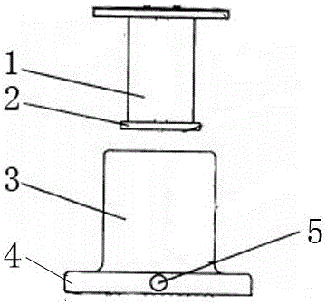
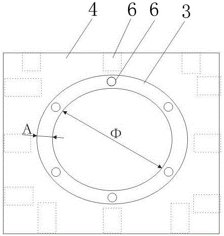
[0027] Such as figure 1 As shown, a kind of equipment for producing polystyrene (PS) pipeline, comprises injection head 1 and injection plastic cylinder 3 below it, and the pressure injection plate 2 is installed at the bottom of described injection head 1, and the bottom of described injection plastic cylinder 3 Set the discharge nozzle 5 and install it on the base 4, the inner diameter of the injection plastic cylinder 3 is φm, the wall thickness is Am, the diameter of the pressure injection plate 2 is φ+A*0.5 / 100~φ+A*1 / 100.

[0028] The inner diameter of the discharge nozzle 5 is φ*1 / 30˜φ*1 / 10.

[0029] The wall thickness A of the plastic injection cylinder 3 is φ*1 / 20˜φ*1 / 10.

[0030] The base plate thickness of the plastic injection cylinder 3 is φ*1 / 10˜φ*1 / 5.

[0031] The downward hydraulic pressure borne by the injection head 1 is φ 2 *10...


PUM


Abstract

The invention discloses a device for producing a polystyrene pipeline. The device comprises an injection head and an injection molding material tank arranged below the injection head. The bottom of the injection head is provided with a pressure injection plate. The bottom of the injection molding material tank is provided with a discharging opening. The discharging opening is installed on a base. The inner diameter of the injection molding material tank is phi (m). The wall thickness of the injection molding material tank is A (m). The diameter of the pressure injection plate is from phi+A*0.5 / 100 to phi+A*1 / 100. Because the fit dimensions between the injection head and the injection molding material tank are improved, the seal performance can be improved, and the work performance is safer and more reliable.

Description

technical field [0001] The invention relates to a plastic pipe forming device, in particular to a device for producing polystyrene (PS) pipes. Background technique [0002] Traditional plastic molding machines generally use the screw to push the piston to form the plastic in the barrel in the mold. The biggest disadvantage of this type of molding machine is that it can only process workpieces less than 30kg in a mold at a time, and cannot process larger plastic products. Secondly, the equipment is expensive. [0003] In order to produce plastic products over 30kg, some companies adopt the design idea that the outer diameter of the injection piston is larger than the inner diameter of the plastic injection cylinder (patent application number is 200310111313.6), thereby expanding the capacity of the material cylinder and injection pressure, and can process 30-500kg of materials at a time Large workpieces are formed in the mold. However, due to the poor fluidity and slow flow...

Claims


Application Information

Patent Timeline
IPC IPC(8): B29C45/46B29C45/58B29C45/74B29C45/20B29L23/00B29K25/00
CPCB29C45/20B29C45/46B29C45/58B29C45/74B29K2025/06B29L2023/22
Inventor 姚桂芳
Owner 姚梓茗
Features
  • R&D
  • Intellectual Property
  • Life Sciences
  • Materials
  • Tech Scout
  • Unparalleled Data Quality
  • Higher Quality Content
  • 60% Fewer Hallucinations
Learn More