
Automatic connection system and method for remote communication of crane

A technology of remote communication and cranes, which is applied in the field of mechanical equipment, can solve problems such as laying optical cables and optical fibers, and achieve the effect of laying safety and improving work efficiency

Active Publication Date: 2017-01-04
武汉港迪智能技术有限公司 +1
View PDF5 Cites 0 Cited by
  • Summary
  • Abstract
  • Description
  • Claims
  • Application Information

AI Technical Summary

Problems solved by technology

[0004] In order to overcome the defects of the above-mentioned background technology, the present invention provides an automatic connection system and method for remote communication of cranes, which solves the problem of laying out cable optical fibers when the crane communicates with the central control room by wire

Method used


Image

  • Automatic connection system and method for remote communication of crane
  • Automatic connection system and method for remote communication of crane
  • Automatic connection system and method for remote communication of crane

Examples


Embodiment 1

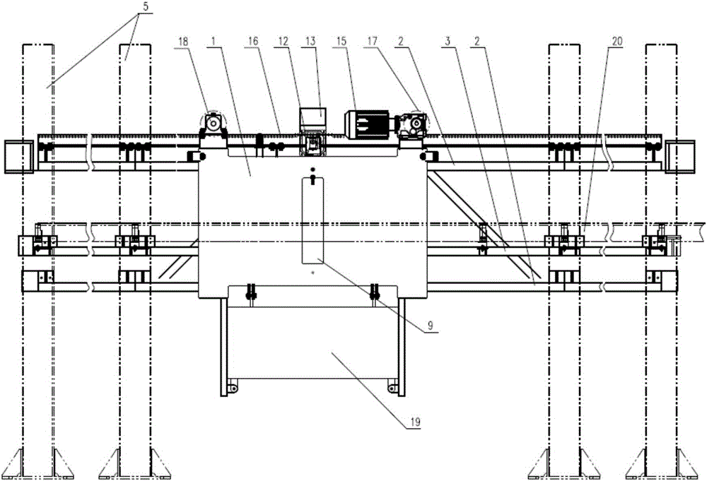
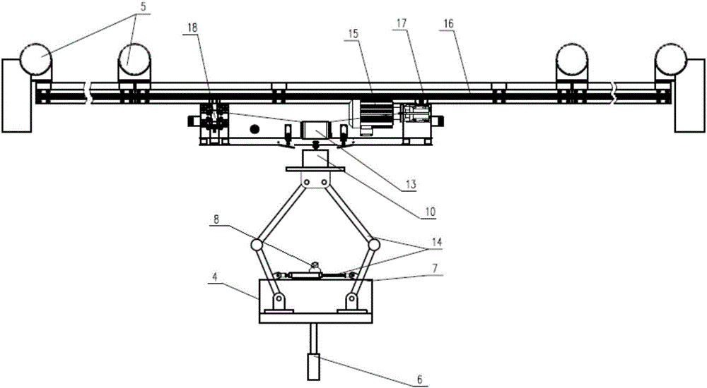
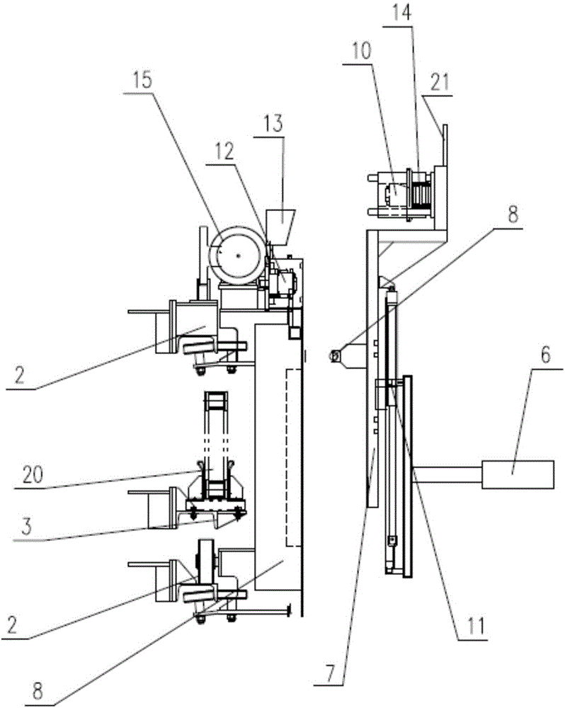
[0028] An automatic connection system for crane remote communication, including a socket 12 arranged on a communication trolley 1 and connected to a controller in a central control room, and a plug 10, socket 12 and a plug arranged on a crane and connected to a crane controller 10 are matched with each other and set facing each other; the cable between the socket 12 and the controller in the central control room is set on the drag chain 20, and the drag chain 20 is arranged along the drag chain track 3; the connecting platform 4 is set on the crane through the main push rod 6 , the plug 10 is set on the connection platform 4, the connection platform 4 is pushed out by the main push rod 6, and the plug 10 can be inserted into the socket 12; 8 match the limit chute 9, and the pressure wheel 8 can be inserted into the limit chute 9; the communication trolley 1 can be driven by the drive motor 15 or the crane to run along the running track 2, and the running track 2 and the drag ch...

Embodiment 2

[0041] An automatic connection method for remote communication of cranes using the system of Embodiment 1:

[0042] After the crane moves to the destination position, the controller in the central control room issues a movement command, and the drive motor 15 executes the movement command to drive the communication trolley 1 to move to the position of the crane; the communication controller 19 controls the laser 13 to continuously emit laser beams. When the laser beam is reflected back by the reflector 21, the communication controller 19 controls the communication car 1 to stop running;

[0043] The crane controller controls the extension of the main push rod 6, so that the pressure roller 8 on the connection platform 4 is close to the panel of the communication trolley 1, and the communication trolley 1 is controlled by the communication controller 19 to move until the pressure roller 8 is inserted into the limit chute 9;

[0044] The crane controller controls the movement of...


PUM


Abstract

The invention provides an automatic connection system and method for remote communication of a crane. The automatic connection system comprises a socket and a plug, wherein the socket is arranged on a communication trolley and connected to a central control room controller, the plug is arranged on the crane and connected to a crane controller, and the socket and the plug are matched with each other and arranged in the face-to-face direction. The crane comprises a connection platform. The plug is arranged at the upper end of the connection platform, a press wheel is further arranged at the upper end of the connection platform, a limiting sliding groove which is matched with the press wheel is formed in the communication trolley, and the press wheel can be inserted into the limiting sliding groove. The communication trolley can be driven by a driving motor or the crane to move along running rails. Cables between the socket and the central control room controller are arranged on a drag chain, the drag chain is arranged along a drag chain rail, and the running rails and the drag chain rail are parallel to the running path of the crane. The purpose of arrangement of optical cables and optical fibers in the process of wire communication between the crane and a central control room is achieved.

Description

technical field [0001] The invention belongs to the field of mechanical equipment, and in particular relates to an automatic docking system and method for remote communication of cranes. Background technique [0002] The safety management of cranes and the efficient and reasonable use of resources are getting more and more attention. At this stage, more and more bridge-gate cranes need to be remotely monitored and managed in the central control room. There are a large number of video signals and control signals on the cranes that need to be transmitted to the central In the control room, how to ensure the real-time and stable transmission of these signals has become a very important issue. Commonly used methods for long-distance signal transmission are wireless communication or optical fiber wired communication. However, the current wireless communication technology cannot meet the clear and stable transmission of a large number of video signals, and the laying of optical ca...

Claims


Application Information

Patent Timeline
IPC IPC(8): B66C13/44B66C13/12
CPCB66C13/12B66C13/44
Inventor 范沛周家智马铭涂铮
Owner 武汉港迪智能技术有限公司
Learn More