Combined fan, electronic equipment and information processing method
A technology for electronic equipment and fans, which is applied in the fields of electrical digital data processing, mechanical equipment, digital data processing components, etc., and can solve problems such as inadvisability
- Summary
- Abstract
- Description
- Claims
- Application Information
AI Technical Summary
Problems solved by technology
Method used
Image
Examples
Embodiment 1
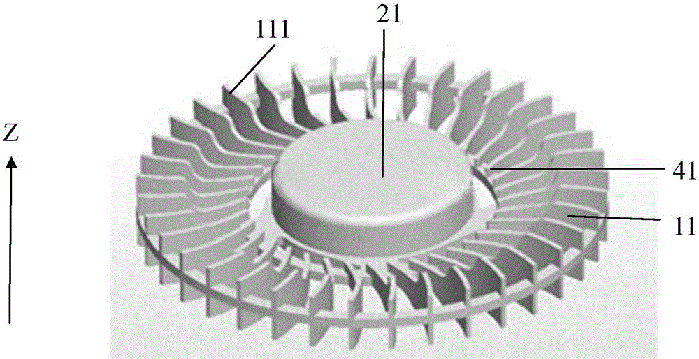
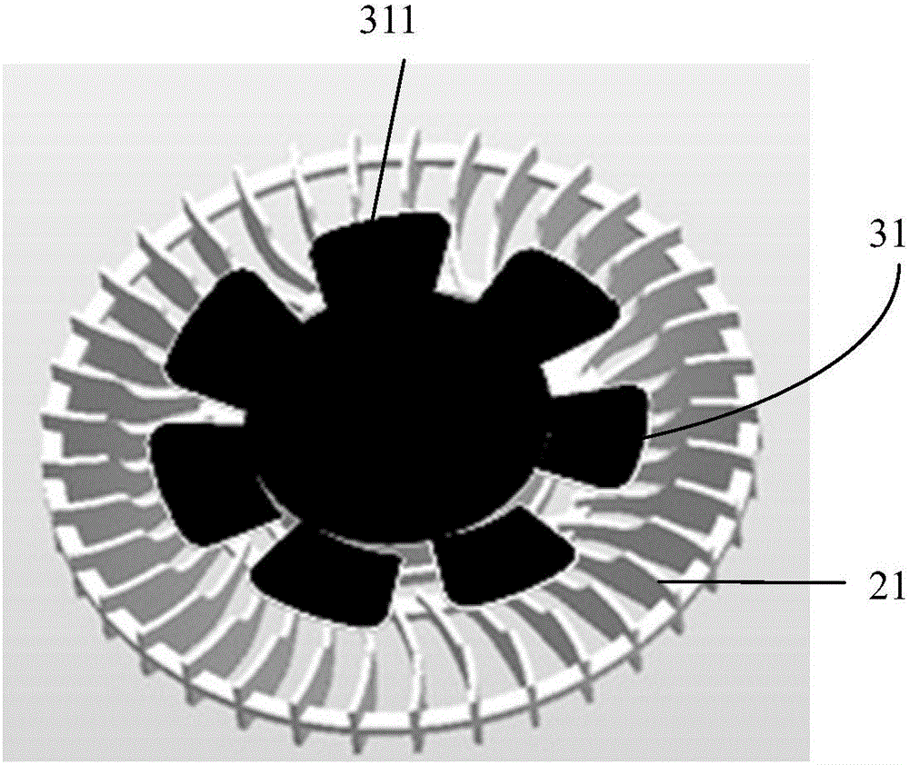
[0037] The embodiment of the present invention provides a composite fan, such as figure 1 and figure 2 As shown, the composite fan includes: a first fan assembly 11 and a second fan assembly 31 arranged coaxially, wherein the first direction of the airflow conducted by the first fan assembly 11 is different from that conducted by the second fan assembly 31 The second direction of the airflow. Wherein, the coaxial axis is the first connecting axis 21 . Wherein, the first fan assembly 11 includes a plurality of centrifugal fan blades 111 , and the second fan assembly 31 includes a plurality of axial flow fan blades 311 . The first connecting shaft 21 may specifically be a bearing. Such as figure 1 As shown, the plurality of centrifugal fan blades 111 can be connected together by an annular connecting piece, and then connected with a bearing, which is called a centrifugal fan.
[0038] Further, such as figure 1 As shown, the first fan assembly 11, specifically the pluralit...
Embodiment 2
[0042] The embodiment of the present invention provides a composite fan, such as figure 1 and figure 2As shown, the composite fan includes: a first fan assembly 11 and a second fan assembly 31 arranged coaxially, wherein the first direction of the airflow conducted by the first fan assembly 11 is different from that conducted by the second fan assembly 31 The second direction of the airflow. Wherein, the coaxial axis is the first connecting axis 21 . Wherein, the first fan assembly 11 includes a plurality of centrifugal fan blades 111 , and the second fan assembly 31 includes a plurality of axial flow fan blades 311 . The first connecting shaft 21 may specifically be a bearing. Such as figure 1 As shown, the plurality of centrifugal fan blades 111 can be connected together by an annular connecting piece, and then connected with a bearing, which is called a centrifugal fan.
[0043] Further, such as figure 1 As shown, the first fan assembly 11, specifically the plurality...
Embodiment 3
[0049] The embodiment of the present invention also provides an electronic device including the aforementioned composite fan. The electronic device can be a notebook computer, an all-in-one computer, a small server, etc., or a desktop computer, a large server, or an industrial control computer. Of course, the electronic equipment also includes equipment with heat dissipation function used in real life, such as household appliances, frequency converters, medical equipment, stage lighting equipment, audio equipment, automatic teller machines ATM machines, large printing equipment and so on. The preferred electronic device in this embodiment may be a notebook computer.
PUM
 Abstract
Description
Claims
Application Information
 - R&D
- Intellectual Property
- Life Sciences
- Materials
- Tech Scout
- Unparalleled Data Quality
- Higher Quality Content
- 60% Fewer Hallucinations
Browse by: Latest US Patents, China's latest patents, Technical Efficacy Thesaurus, Application Domain, Technology Topic, Popular Technical Reports.
© 2025 PatSnap. All rights reserved.Legal|Privacy policy|Modern Slavery Act Transparency Statement|Sitemap|About US| Contact US: help@patsnap.com


