Clamping-connection rotary disc for calcination of U-shaped bolt

A chuck and bolt technology, which is applied in the field of U-bolt calcining and clamping rotary disc, which can solve the problems of inconvenient U-shaped bolt calcining and inconvenient clamping, etc.

Active Publication Date: 2017-01-04
靖江市西来农创运营管理有限公司
View PDF5 Cites 2 Cited by
  • Summary
  • Abstract
  • Description
  • Claims
  • Application Information

AI Technical Summary

Problems solved by technology

The existing u-shaped bolts are inconvenient to clamp,

Method used


Image

  • Clamping-connection rotary disc for calcination of U-shaped bolt
  • Clamping-connection rotary disc for calcination of U-shaped bolt
  • Clamping-connection rotary disc for calcination of U-shaped bolt

Examples


Embodiment Construction

[0016] The preferred embodiments of the present invention will be described in detail below in conjunction with the accompanying drawings, so that the advantages and features of the present invention can be more easily understood by those skilled in the art, so as to define the protection scope of the present invention more clearly.

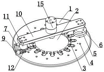
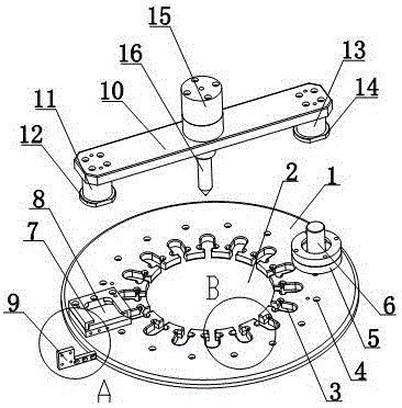
[0017] like Figure 1 to Figure 4 As shown, a U-shaped bolt calcined and clamped rotating disk includes a chuck 1. The axial position of the chuck 1 is provided with a slot 2; The slot 2 is connected; one side of the chuck 1 is provided with a fixed ring 5, the fixed ring 5 is provided with a positioning shaft 6, the other side of the chuck 1 is provided with a card seat 7, and the card seat 7 is provided with a card cavity 8. There is a first connecting column 11 on the deck 7, and a snap ring 12 is provided at the lower end of the first connecting post 11. The snap ring 12 is snapped at the position of the card cavity 8, and the outer periphera...


PUM


Abstract

The invention discloses a clamping-connection rotary disc for calcination of a U-shaped bolt. The clamping-connection rotary disc comprises a chuck, and an open groove is formed in the axial position of the chuck. Multiple clamping grooves are formed in the axial position of the chuck, and the clamping grooves communicate with the open groove. A fixing ring is arranged on one side of the chuck, a positioning shaft is arranged on the fixing ring, a clamping base is arranged on the other side of the chuck, and a clamping cavity is formed in the clamping base. A first connecting column is arranged on the clamping base, a clamping ring is arranged at the lower end of the first connecting column, and the clamping ring is connected to the position of the clamping cavity in a clamped manner. The outer circumferential face of the positioning shaft is sleeved with a second connecting column, the second connecting column is parallel to the first connecting column, and a butt joint plate is arranged between the end of the second connecting column and the end of the first connecting column. A fixing cap is arranged on the upper portion of the butt joint plate, and a drive shaft is arranged on the lower portion of the butt joint plate. The lower end of the drive shaft serves as a free end, and the upper end of the drive shaft is connected with the fixing cap. The rotary disc is installed in a calcinator, so that the U-shaped bolt is convenient to calcine.

Description

technical field [0001] The invention relates to a U-shaped bolt manufacturing equipment, in particular to a U-shaped bolt calcined and clamped rotating disk. Background technique [0002] U-shaped bolts are saddle bolts. They are U-shaped, so they are also called U-shaped bolts. There are threads at both ends that can be combined with nuts. They are mainly used to fix tubular objects such as water pipes or sheet objects such as leaf springs of automobiles. The existing u-shaped bolts are inconvenient to clamp, and it is inconvenient to calcinate the u-shaped bolts. Contents of the invention [0003] The present invention mainly solves the technical problems existing in the prior art, thereby providing a driving motor that can conveniently control the rotation of the drive shaft, and can clamp the U-shaped bolts to be processed in the clamping groove, thereby facilitating the U-shaped bolts to be processed. The rotation of the bolts is controlled, and the rotating disk is ...

Claims


Application Information

Patent Timeline
IPC IPC(8): F27D5/00
CPCF27D5/00F27D5/005
Inventor 李健
Owner 靖江市西来农创运营管理有限公司
Why Eureka
Try Eureka