Mounting frame for spur rack calcination

A technology of mounting frame and straight rack, which is applied in the direction of furnace, charge processing type, furnace material, etc., and can solve the problems of inconvenient installation and inconvenient calcination of straight rack

Inactive Publication Date: 2017-06-20
于法周
View PDF4 Cites 0 Cited by
  • Summary
  • Abstract
  • Description
  • Claims
  • Application Information

AI Technical Summary

Problems solved by technology

The existing racks, especially the straight racks, are inconvenien...

Method used


Image

  • Mounting frame for spur rack calcination
  • Mounting frame for spur rack calcination
  • Mounting frame for spur rack calcination

Examples


Embodiment Construction

[0018] The preferred embodiments of the present invention will be described in detail below in conjunction with the accompanying drawings, so that the advantages and features of the present invention can be more easily understood by those skilled in the art, so as to define the protection scope of the present invention more clearly.

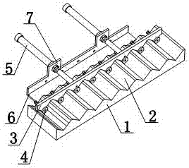
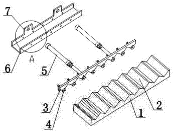
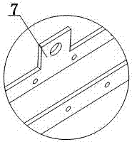
[0019] Such as Figure 1 to Figure 6 As shown, a mounting frame for spur rack calcination includes a mounting base 1 and a mounting mechanism, the mounting base 1 is provided with a number of mounting grooves 2, the mounting mechanism includes a push plate 3 and a fixing mechanism 5, and the fixing mechanism 5 includes a fixing mechanism cylinder 13, the front portion of the fixed cylinder 13 is provided with a connecting shaft 14, the push plate 3 is arranged on the mounting seat 1, the lower part of the push plate 3 is provided with a bump 8, and the bump 8 is arranged at the position of the installation groove 2, and the push plate 3 The rear ...


PUM


Abstract

The invention discloses a mounting frame for calcining a straight rack, comprising a mounting seat and a mounting mechanism, a plurality of mounting grooves are arranged on the mounting seat, the mounting mechanism includes a push plate and a fixing mechanism, the fixing mechanism includes a fixing cylinder, and the The front part is provided with a connecting shaft, the push plate is set on the mounting seat, the lower part of the push plate is provided with a bump, the bump is set at the position of the installation groove, the rear part of the push plate is provided with a fixing rod, and the fixing rod is connected with the connecting shaft; The plate is provided with a fixing piece, the fixing piece includes a fixing pin, one end of the fixing pin is provided with a lock ring, and the other end of the fixing pin is provided with a lock cap; a fixing frame is arranged between the mounting seat and the fixing mechanism, and the upper part of the fixing frame is provided with The convex piece is arranged between the fixing cylinder and the connecting shaft; the fixing pin is connected with the fixing frame, and the locking cap is arranged on the inner side wall of the fixing frame. In the present invention, the spur gear rack to be processed is placed at the position of the installation groove on the mounting seat, and the spur gear rack can be placed in the calcining furnace, so that the spur gear rack can be calcined conveniently.

Description

technical field [0001] The invention relates to a rack processing equipment, in particular to a mounting frame for calcining a straight rack. Background technique [0002] The rack is a special gear with teeth distributed on the bar-shaped body; the rack is also divided into a straight tooth rack and a helical tooth rack, which are paired with a straight tooth cylindrical gear and a helical tooth cylindrical gear respectively. The existing racks, especially the straight racks, are inconvenient to install, and it is also inconvenient to calcinate the straight racks. Contents of the invention [0003] The present invention mainly solves the technical problems existing in the prior art, thereby providing a mounting groove position where the spur rack to be processed can be placed on the mounting seat, and the spur rack can be placed in the calciner, thereby facilitating Mounting frame for firing spur racks for firing the spur racks. [0004] Above-mentioned technical proble...

Claims


Application Information

Patent Timeline
IPC IPC(8): F27D5/00
CPCF27D5/00F27M2003/03
Inventor 于法周
Owner 于法周
Why Eureka
Try Eureka