A mold and test block manufacturing method capable of accurately fixing joint shear test specimens

A shear test and mold technology, applied in the field of rock mass mechanical performance test, can solve the problems of difficult to ensure the accurate occlusion of the joint surface of the test piece, the depth of the test piece buried in the mortar cannot be guaranteed, and the joint surface occlusion is not tight enough, etc. Fast and convenient, ensure reliability, avoid blocking effect

Active Publication Date: 2019-01-25
TONGJI UNIV
View PDF7 Cites 0 Cited by
  • Summary
  • Abstract
  • Description
  • Claims
  • Application Information

AI Technical Summary

Problems solved by technology

For regular cube and cuboid shape specimens, this method is somewhat operable; however, for irregular shape specimens, this method is difficult to ensure the accurate occlusion of the joint surfaces of the two test pieces
In addition, during the mortar curing and forming process, the joint specimen will naturally sink under the action of gravity, and the depth of the specimen embedded in the mortar cannot be guaranteed, resulting in insufficient occlusion or misalignment of the joint surfaces, which is not conducive to obtaining reliable test results

Method used


Image

  • A mold and test block manufacturing method capable of accurately fixing joint shear test specimens
  • A mold and test block manufacturing method capable of accurately fixing joint shear test specimens
  • A mold and test block manufacturing method capable of accurately fixing joint shear test specimens

Examples


Embodiment 1

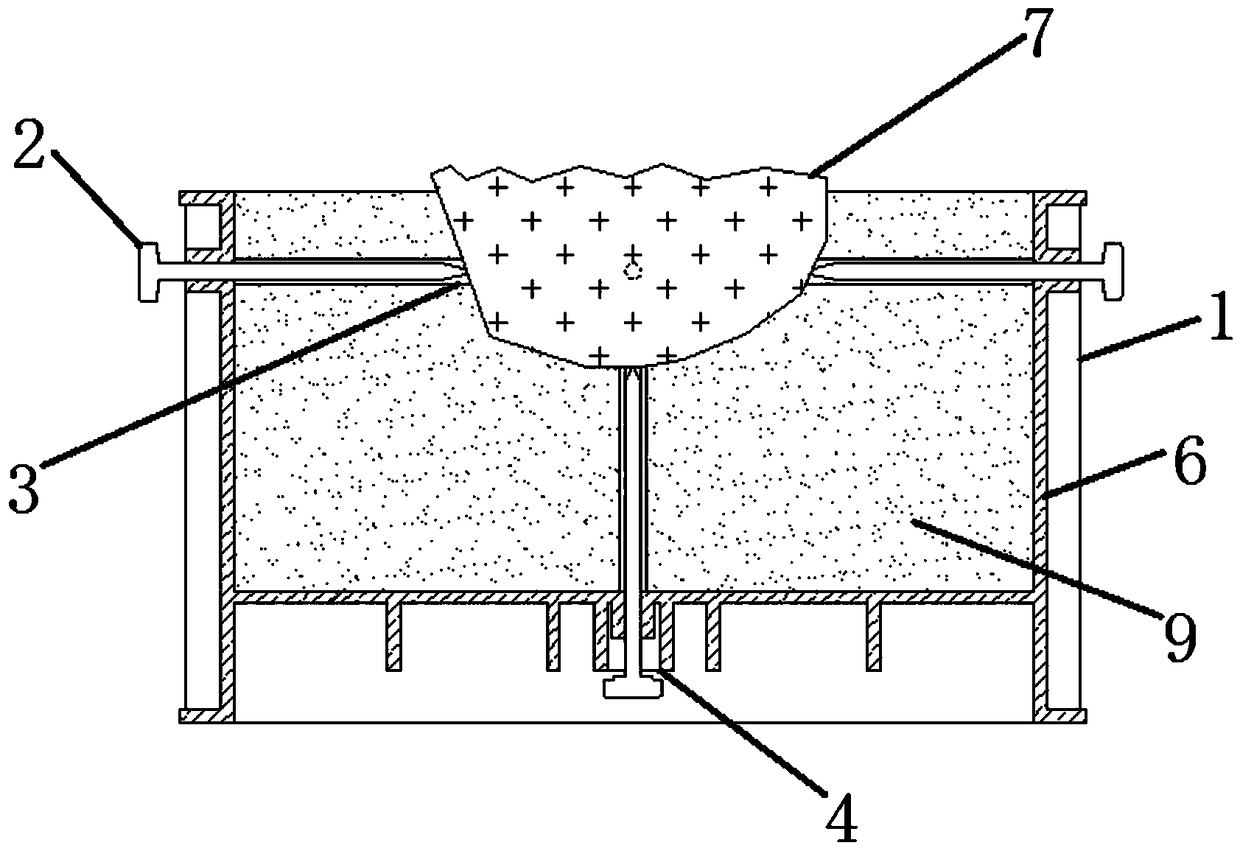
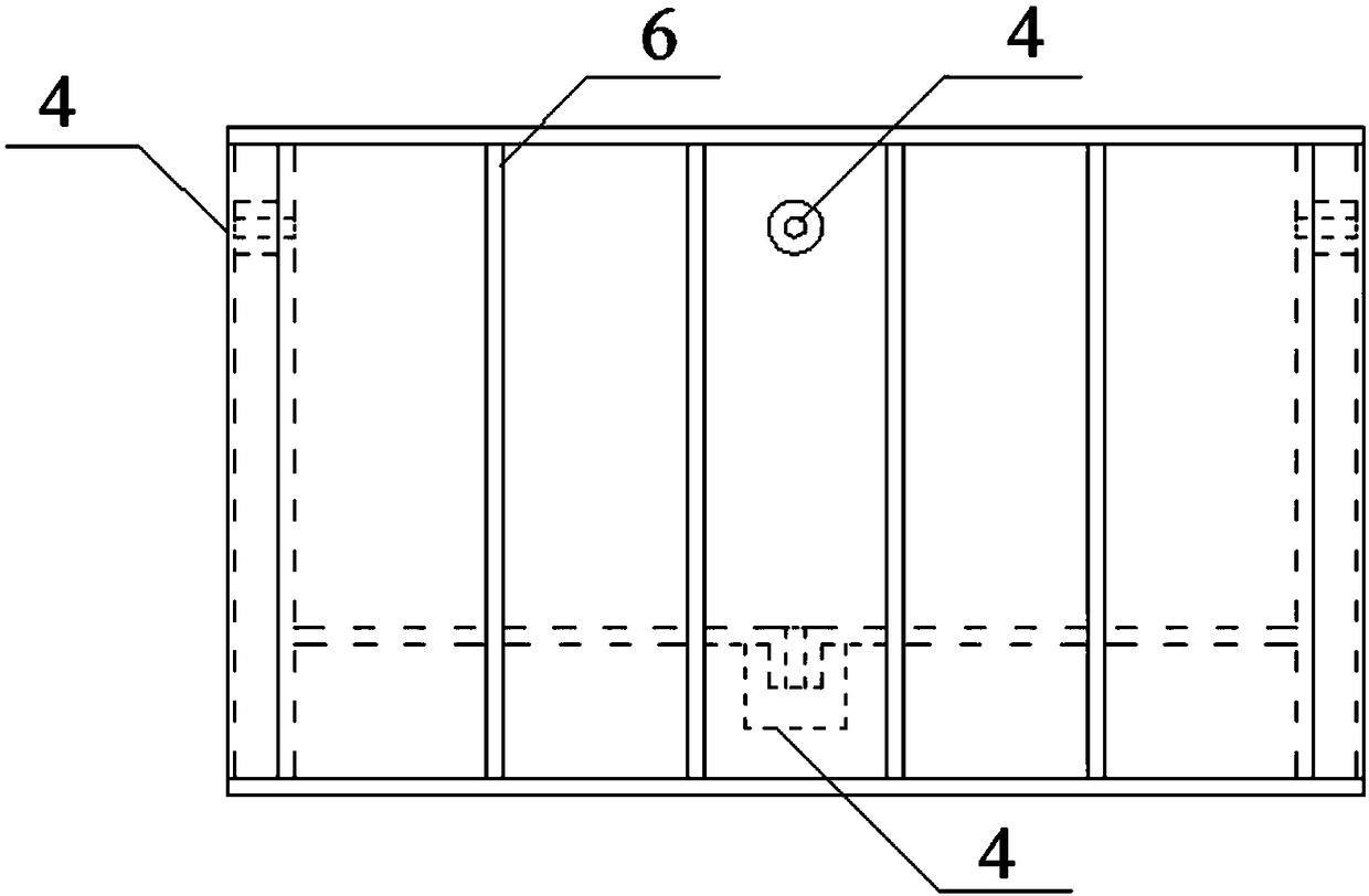
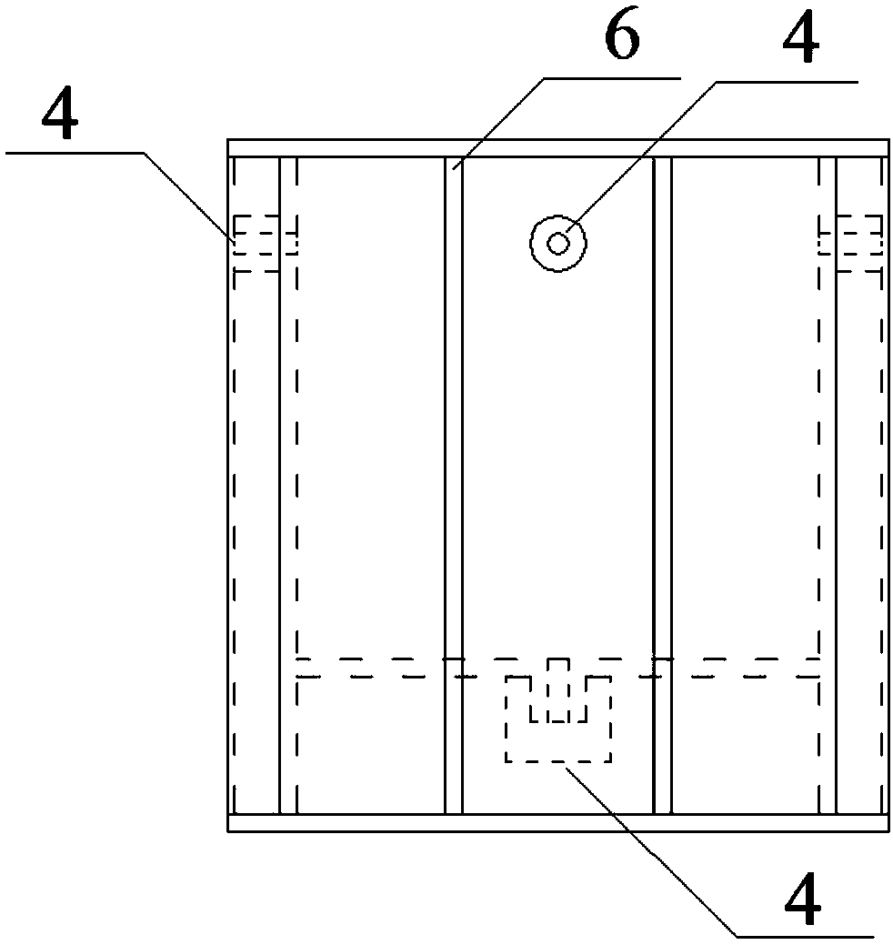
[0043] Such as Figure 1-4 Shown is a mold that can accurately fix joint shear test specimens. The mold includes a mold body 1 with an open upper end. Limit bolt holes 4 are provided on the side and bottom surfaces of the mold body 1. Inside the limit bolt holes 4 are The limit bolt 2, the structure of the limit bolt 2 is as follows Figure 5 Shown in (a).

[0044] Wherein, the mold main body 1 is a rectangular mold main body with an upper end opening, and limit bolt holes 4 are provided on the four sides and the bottom surface of the rectangular mold main body. The limit bolt hole 4 on the side of the mold main body 1 is located on the vertical central axis of the corresponding side, and the distance from the top of the side is 30mm. The limit bolt hole 4 on the bottom surface of the mold main body 1 is located at the center of the bottom surface.

[0045] The length of the threaded section of the limit bolt 2 is 50mm. The outer sleeve of the limit bolt 2 is provided with...

Embodiment 2

[0058] In this embodiment, the limit bolt hole 4 on the side of the mold main body 1 is located on the vertical central axis of the corresponding side, and the distance from the top of the side is 20mm, the length of the threaded section of the limit bolt 2 is 30mm, and the rest are the same as in the embodiment 1.

Embodiment 3

[0060] In this embodiment, the limit bolt hole 4 on the side of the mold main body 1 is located on the vertical central axis of the corresponding side, and the distance from the top of the side is 40mm, the length of the threaded section of the limit bolt 2 is 40mm, and the rest are the same as in the embodiment 1.


PUM

PropertyMeasurementUnit
lengthaaaaaaaaaa
lengthaaaaaaaaaa

Abstract

The invention relates to a mold capable of accurately fixing a test piece of a joint shear test and a production method of a test block. The mold comprises a mold main body with an opened upper end, wherein limiting bolt holes are formed in the side surface and bottom surface of the mold main body, and limiting bolts are arranged in the limiting bolt holes; and by respectively regulating the lengths of the limiting bolts, stretching into the mold main body, on the side surface and bottom surface of the mold, the limiting bolts prop against the surfaces of the test piece of the joint shear test, so as to accurately fix the test piece. The production method comprises the steps of firstly respectively accurately fixing an upper-half joint test piece and a lower-half joint test piece by virtue of an upper mold and a lower mold, lengthening a limiting bolt sleeve sleeving the outside of each limiting bolt, filling the mold with mortar, unscrewing each limiting bolt after the initial setting of the mortar, further carrying out maintenance formation, and removing the mold. Compared with the prior art, the mold has the advantages that the test piece of the joint shear test can be accurately fixed, and the natural sinking of the test piece under the gravity can be effectively prevented; and the operation is simple and convenient, and the reliability is high.

Description

technical field [0001] The invention belongs to the technical field of rock mass mechanical performance testing, and relates to a mold and a test block manufacturing method capable of accurately fixing joint shear test specimens. Background technique [0002] The shear strength of rock joint surfaces and their fillings is one of the key issues in the field of rock mechanics. Rock joint shear tests use alternative materials such as raw rock or concrete as specimens. Mortar pouring was carried out in advance to make two test blocks. After curing and forming, the joint surfaces of the upper and lower half joint test pieces were accurately occluded and then the shear test was carried out. During the occlusal process of the joint surfaces of the upper and lower half joint specimens, the position of the joint surfaces needs to be precisely positioned to ensure accurate and reliable test results. Usually a standard 150mm×150mm×300mm cuboid test block mold is used, and after visual...

Claims


Application Information

Patent Timeline
Patent Type & Authority Patents(China)
IPC IPC(8): G01N1/36
CPCG01N1/36G01N2001/366
Inventor 夏才初李强沈世伟吕志涛
Owner TONGJI UNIV
Why Eureka
Try Eureka