
Operation state monitoring method of railway through line cable

A technology of running state and line, applied in the direction of detecting faults and fault locations according to conductor types, can solve the problems of difficult monitoring of detection devices, and achieve the effect of reducing the false alarm rate, reducing the false alarm rate of faults, and improving the accuracy of the alarm

Active Publication Date: 2017-01-04
山东博鸿电气股份有限公司
View PDF6 Cites 9 Cited by
  • Summary
  • Abstract
  • Description
  • Claims
  • Application Information

AI Technical Summary

Problems solved by technology

[0004] At present, before the permanent grounding fault occurs in the high-speed railway through-cable, there are many breakdowns caused by the cracking of the main insulation in a very short period of time. After the breakdown, the main insulation can recover quickly, making it difficult for general detection devices to monitor.

Method used


Image

  • Operation state monitoring method of railway through line cable
  • Operation state monitoring method of railway through line cable
  • Operation state monitoring method of railway through line cable

Examples


Embodiment 1

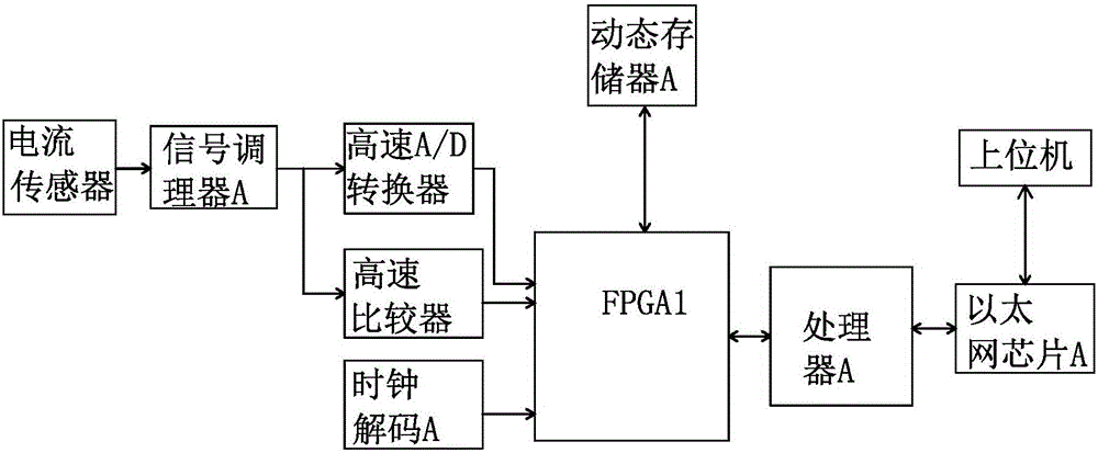
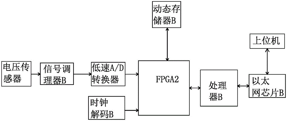
[0031] Such as Figure 1-3 As shown, the method for monitoring the running status of railway through-line cables includes high-speed railway through-line cables, box substations and / or signal stations, and substations. Voltage sensors are set on the high-speed railway through-line cable bus PTs in substations to collect zero-sequence voltage transients Signals, current sensors are installed in each box substation and / or signal station to collect the electromagnetic transient signal of each section of high-speed railway through-line cable flowing through the metal shielding layer.

[0032] The electromagnetic transient signal collected by the current sensor is transmitted to the railway power supply host computer system platform through the high-speed railway through-line operation status monitoring device. The high-speed railway running state monitoring device includes a circuit-connected signal conditioner A, a high-speed A / D converter, a high-speed comparator, FPGA1, a clock...

Embodiment 2

[0046] On the basis of Embodiment 1, set according to the actual situation of the high-speed railway through-line cable, the trigger condition refers to that the zero-sequence voltage signal is analyzed by the waveform, and the change trend of the waveform meets the empirical value; the displayed waveform change speed or rise speed, Sampling points per unit time, the data difference between the first point and the fourth point is greater than 50.

Embodiment 3

[0048] On the basis of the above examples, the trigger condition is modified to zero-sequence voltage signal. After waveform analysis, the pulse rising speed reaches 1.465V within 3μs, and continues to be greater than 5.859V within 7μs.


PUM


Abstract

The invention provides an operation state monitoring method of a railway through line cable and belongs to the field of on-line monitoring of the railway through line cable. The operation state monitoring method comprises a high-speed railway through line cable and is characterized in that by detecting a bus PT zero-sequence voltage transient-state signal of the railway through line cable is generated or not, whether an instantaneity transient-stat fault occurs to the high-speed railway through line cable is judged; and by monitoring and recording electromagnetic transient-state signal which is generated by the high-speed railway through line cable and flows through a metal shielding layer, fault early warning is performed on the high-speed railway through line cable and the fault point distance is indicated. Compared with the original cable operation state monitoring method, the operation state monitoring method provided by the invention is advantageous in that early warning can be given to an instantaneity transient-stat grounding fault before a cable is damaged; non-fault disturbance signals generated by passing of a train, reclosing and the like can be filtered; system misinformation caused by disturbance is effectively reduced; alarm accuracy is improved; and false alarm rate is reduced.

Description

technical field [0001] The invention belongs to the field of on-line monitoring of railway through-lines, and specifically relates to a method for monitoring the running status of cables on railway through-lines Background technique [0002] The through line on the railway is used to directly provide a reliable and uninterrupted power supply for the electrical centralized equipment of each railway station and the self-closing signal point of the section. It is an important part of the railway power system. Its power supply reliability not only directly affects the railway locomotive It also affects the power supply and distribution work inside the railway, which is an important matter related to railway transportation. [0003] Railway transportation is developing towards high speed and high density. Ensuring reliable power supply of power supply lines is the basic condition for ensuring safe and punctual train operation. The traditional line monitoring method adopts the me...

Claims


Application Information

Patent Timeline
IPC IPC(8): G01R31/08
CPCG01R31/083
Inventor 魏洪文张立斌厉新波王勃马加庆渠忠磊李玮
Owner 山东博鸿电气股份有限公司
Learn More