Suspension positioning mechanism

A technology of positioning mechanism and positioning parts, applied in installation, optics, instruments and other directions, can solve the problems of difficult to disassemble and assemble moving parts, the roller has no adjustment function, and there is no lifting mechanism, so as to improve the repeated positioning and disassembly speed, improve the The effect of positioning stability and reliability, simple and convenient operation

Active Publication Date: 2017-01-04
SHANGHAI MICRO ELECTRONICS EQUIP (GRP) CO LTD
View PDF8 Cites 5 Cited by
  • Summary
  • Abstract
  • Description
  • Claims
  • Application Information

AI Technical Summary

Problems solved by technology

However, there are still three problems with this positioning device: one is that two fixed planes are used for side positioning, and the positioning accuracy is low; the other is that there is no lifting mechanism for disassembly, and it is not easy to disassemble and assemble the moving parts; The rollers have no adjustment function, and there is a risk of collision with parts above the fixed components during assembly

Method used


Image

  • Suspension positioning mechanism
  • Suspension positioning mechanism
  • Suspension positioning mechanism

Examples


Embodiment Construction

[0032] The present invention is described in detail below in conjunction with accompanying drawing:

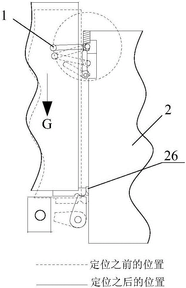
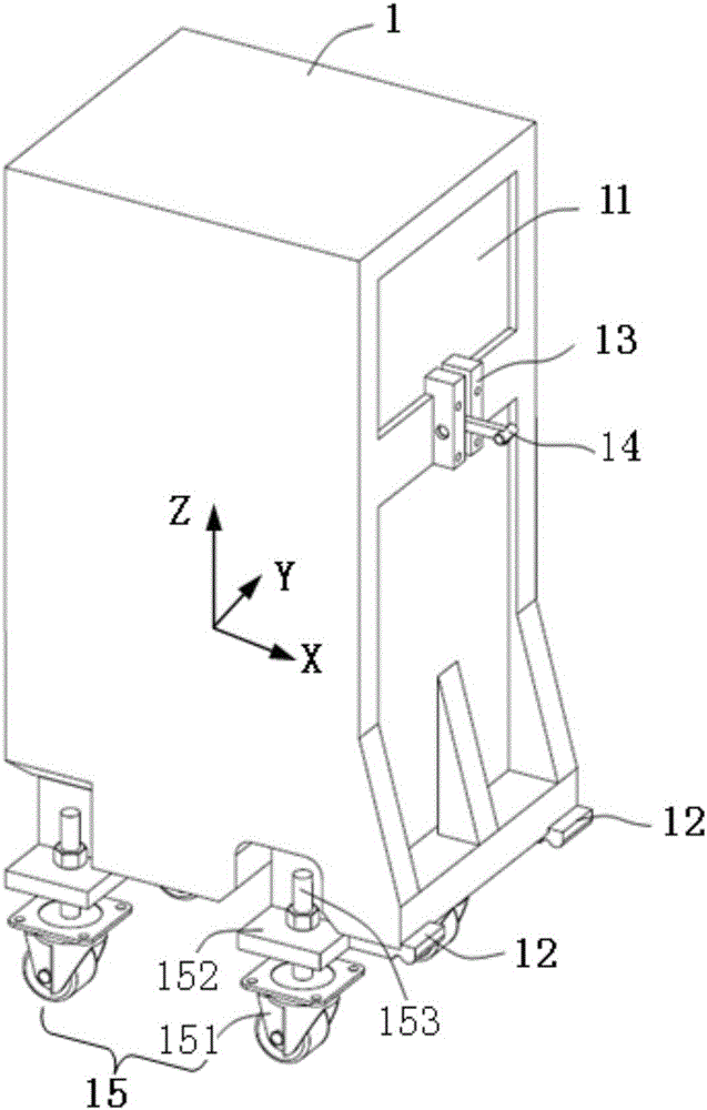
[0033] like figure 1 , 4 As shown, the present invention provides a suspension positioning mechanism, which includes a moving assembly 1 and a stationary assembly 2 .

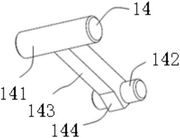
[0034] Wherein the moving assembly 1 comprises a body 11, at least two contact blocks 12 arranged on one side of the body 11, a groove 13, a hook 14 with one end accommodated in the groove 13, and several height-adjustable pulley blocks arranged at the bottom of the body 11 piece 15. like figure 2 As shown, the hook 14 is in the shape of a "worker" as a whole, including a fixed end 141 fixed in the groove 13, a free end 142 and a connecting portion 143 connecting the fixed end 141 and the free end 142, and the connecting portion 143 extends to the free end 142. The outer edge, and a flange 144 is provided at the bottom near the free end 142 . Specifically, two L-shaped baffles are set in the groove 13, an...


PUM


Abstract

The invention discloses a suspension positioning mechanism, which comprises a motion assembly and a fixed assembly, and is characterized in that the motion assembly comprises a body, at least two contact blocks arranged at one side of the body, a groove, a hook with one end being accommodated in the groove, and a plurality of height adjustable sliding wheel assemblies arranged at the bottom of the body; one side of the fixed assembly comprises supporting assemblies, a lifting assembly, a hook positioning assembly, a hook shifting lever assembly, an X-direction positioning member and a Y-direction positioning member, wherein the supporting assemblies and the lifting assembly are matched with the contact blocks, the hook positioning assembly and the hook shifting lever assembly are matched with the hook, and the X-direction positioning member and the Y-direction positioning member are used for positioning the motion assembly. According to the invention, the positioning stability and the reliability of the motion assembly can be effectively improved through setting the contact blocks and the supporting assemblies with a balancing function, and the lifting assembly is set at the same time so as to improve the repeat positioning, assembling and disassembling speed of an optical system; and the plurality of height adjustable sliding wheel assemblies are adopted, so that the overall position of the motion assembly is effectively adjusted, the motion assembly is prevented from colliding with a part above the fixed assembly in the positioning process, the operation is simple and convenient, and the effect is stable and reliable.

Description

technical field [0001] The invention relates to the field of positioning of optical systems, in particular to a suspension positioning mechanism. Background technique [0002] Positioning of a moving module relative to a stationary module is often required in semiconductor manufacturing. Usually, due to limitations such as space structure, in the docking of the optical system, it is often necessary to fix and position the side of the system. Due to the requirements of the entire assembly, testing, transportation and maintenance of the optical system, multiple disassembly and positioning are often required between the systems, which requires the positioning mechanism to meet high repeat positioning accuracy. [0003] In traditional side positioning devices, tooling is generally used for positioning. This positioning method is to first install a tooling on the fixed component, then move the moving component to the tooling, combine the moving component with the fixed componen...

Claims


Application Information

Patent Timeline
Patent Type & Authority Applications(China)
IPC IPC(8): G02B7/00H01L21/68
Inventor 李素平刘剑
Owner SHANGHAI MICRO ELECTRONICS EQUIP (GRP) CO LTD
Why Eureka
Try Eureka