
Obstacle dodging method of UAV based on velocity obstacle arc method

A technology for unmanned aerial vehicles and speed obstacles, applied in the direction of instruments, vehicle position/route/height control, non-electric variable control, etc., can solve complex problems such as multi-obstacle collision avoidance, improve autonomous obstacle avoidance ability, simplify collision avoidance problem effect

Active Publication Date: 2017-01-04
NAVAL AVIATION UNIV
View PDF6 Cites 23 Cited by
  • Summary
  • Abstract
  • Description
  • Claims
  • Application Information

AI Technical Summary

Problems solved by technology

[0007] The purpose of the present invention is to provide an unmanned aerial vehicle obstacle avoidance method, which can effectively avoid the impact of ignoring "potentially dangerous" obstacles in the existing obstacle avoidance algorithm, and can solve the complex problem of multi-obstacle collision avoidance

Method used


Image

  • Obstacle dodging method of UAV based on velocity obstacle arc method
  • Obstacle dodging method of UAV based on velocity obstacle arc method
  • Obstacle dodging method of UAV based on velocity obstacle arc method

Examples


Embodiment 1

[0104] Example 1: Collision avoidance of a single level 1 threat obstacle by UAV

[0105] i) Does not consider the impact of secondary and tertiary threat obstacles

[0106] UAV in flight to P u At (200,400), an obstacle O is detected. The obstacle information obtained by the carried sensor device is: position coordinates P o (113.9,522.8), velocity vector size||v o ||=40, speed direction angle β o =15°, puffing radius R=45; in addition, the information of UAV itself is: velocity vector size||v u ||=55, speed direction angle β u = 63.4°. Then, according to the speed obstacle arc method, it can be calculated that the known obstacle is a first-level threat obstacle, and the UAV needs to avoid collision with the threat obstacle.

[0107] By calculating the arc parameters of speed obstacles, the arc parameters of known obstacles G=(50.6, 84.1°, 23.1°) can be obtained. Then, the obstacle avoidance direction range at the obstacle avoidance point can be determined from the ob...

Embodiment 2

[0116] Example 2: Collision Avoidance of UAVs to Multiple Level 1 Threat Obstacles

[0117] i) Does not consider the impact of secondary and tertiary threat obstacles

[0118] When the UAV is in flight to P u (200,400) when two threatening obstacles are detected at the same time. First, the information of the obstacle determined by the sensor device is: position coordinates P o1(114.0,522.9), P o2 (322.9,486.0); Velocity vector size ||v o1 ||=40、||v o2 ||=35; speed direction angle β o1 = 15°, β o2 =125°; Expansion radius R 1 = 45, R 2 =35. According to the speed obstacle arc method, it can be calculated that the two known obstacles are both level-1 threat obstacles, and the UAV needs to avoid collision between the two threat obstacles.

[0119] According to the calculation method of the arc parameters of speed obstacles, the arc parameters of the corresponding two known first-level threat obstacles are G 1 =(50.6,84.1°,23.1°), G 2 =(53.4,72.2°,13.5°). Then, the ob...


PUM


Abstract

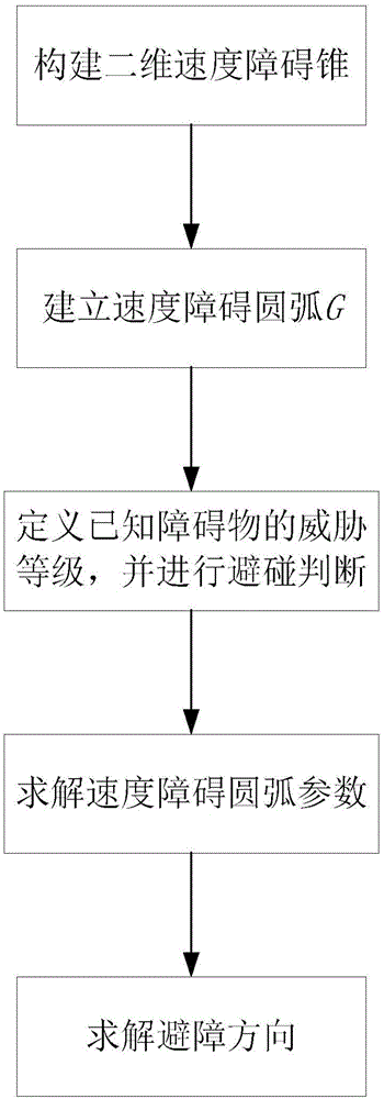
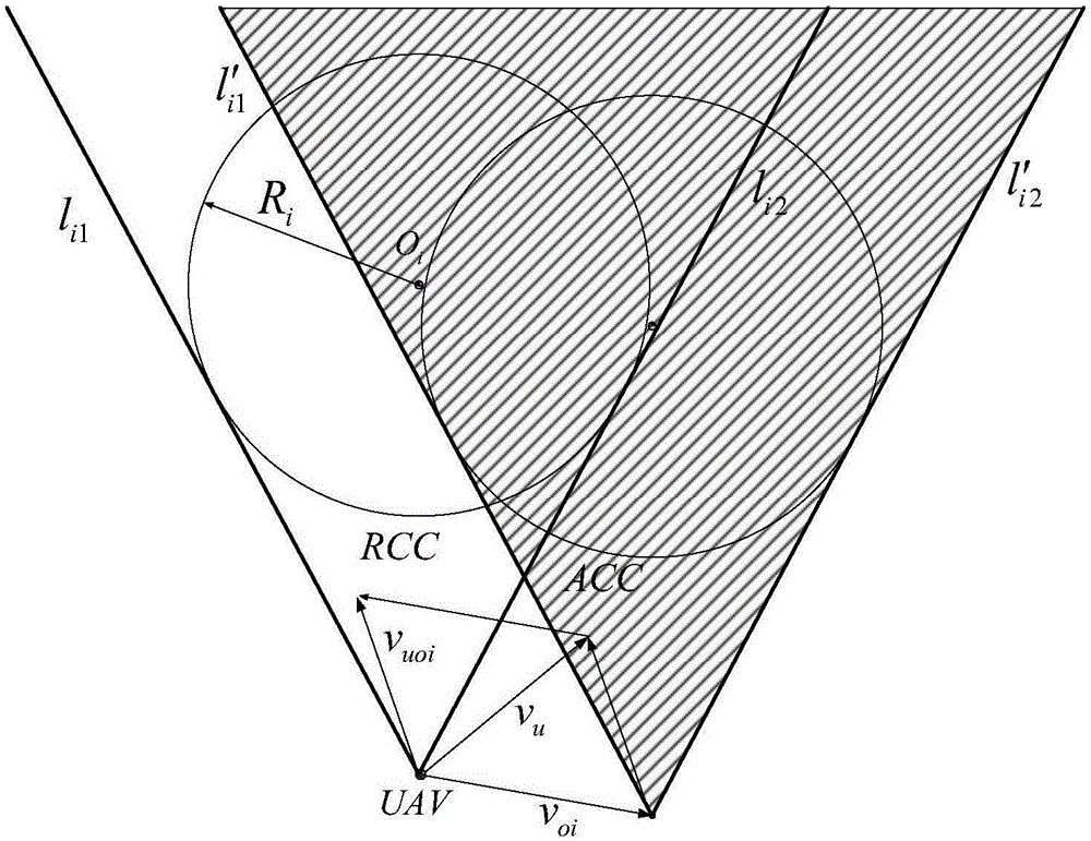
The invention discloses an obstacle dodging method of UAV based on the velocity obstacle arc method. The obstacle dodging method mainly comprises the following steps: establishing a 2-dimensional barrier cone; establishing the velocity obstacle arc; defining the ranking of known obstacle threats and implementing the judgment for dodging activity; solving the arc parameters of the velocity obstacle; solving the dodging direction. And the known obstacles are classified into three levels of obstacle threats, the level I obstacle threat must be dodged; the level II obstacle shall receive the analysis as to the impact incurred from the UAV dodging process; the level III obstacle doesn't need to be dodged at all. The method can effectively avoid the negative influences brought by the negligence of 'potential dangers' characterized by the prior art of obstacle dodging algorithms, and can solve the complex tasks of dodging multiple obstacles, the method can hugely upgrade the self dodging capability of UAV under complex environment.

Description

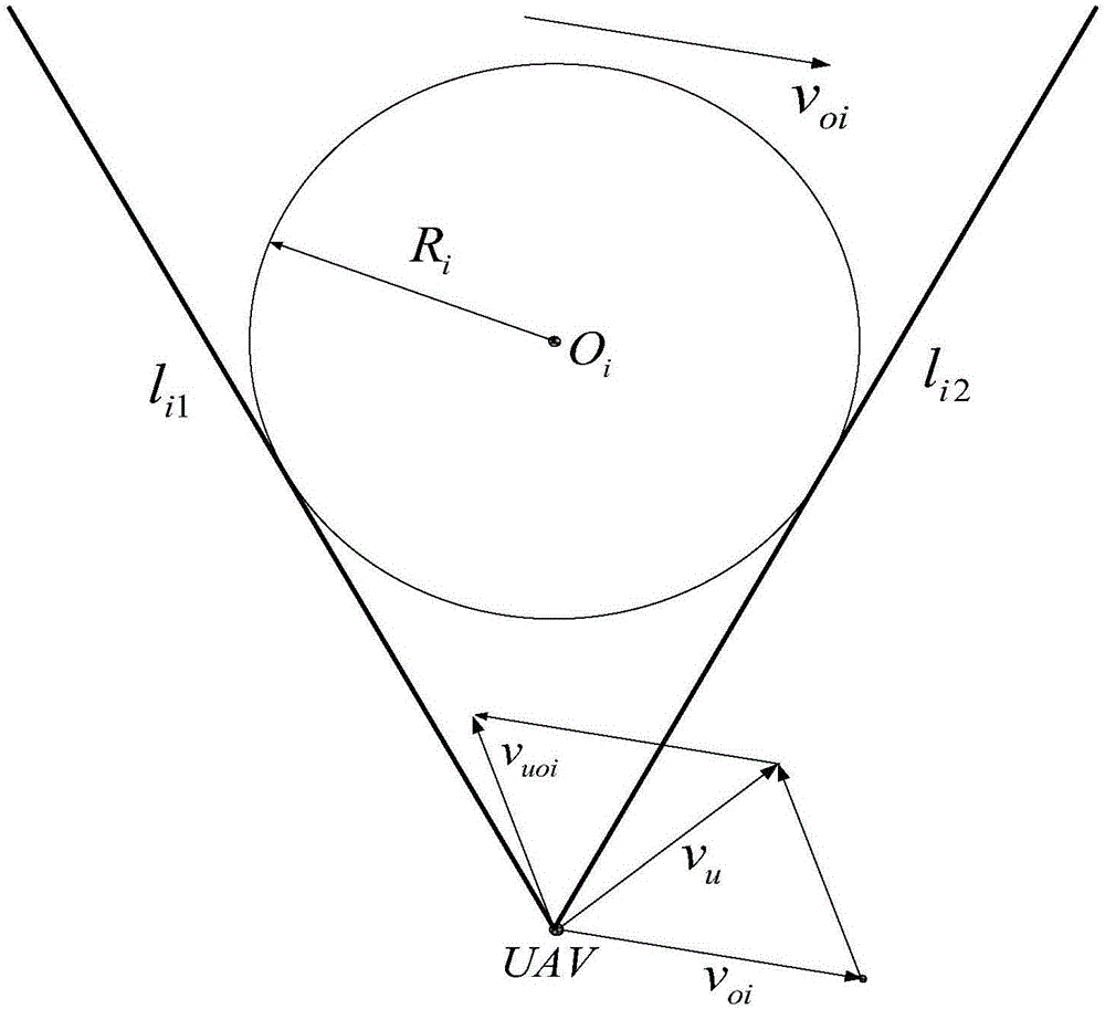
technical field [0001] The invention belongs to the control field of unmanned aircraft space obstacle avoidance flight, and in particular relates to an unmanned aircraft obstacle avoidance method based on the speed obstacle arc method, which is aimed at the problem of unmanned aircraft obstacle avoidance in a two-dimensional plane. Background technique [0002] During the mission flight, the unmanned aerial vehicle can use the sensor device carried by itself to detect the dynamic and static obstacles around (the obstacles detected by the unmanned aerial vehicle will be referred to as known obstacles in the following), these dynamic and static obstacles may It will affect the safe flight of unmanned aerial vehicles. Usually, in order to simplify the judgment of the obstacle threat, the unmanned aerial vehicle is assumed to be a particle, and its current position coordinates are P u (x u ,y u ), and the known obstacle point O according to the relative size between the UAV a...

Claims


Application Information

Patent Timeline
IPC IPC(8): G05D1/10
CPCG05D1/101G05D1/106
Inventor 杨秀霞周硙硙张毅华伟梁勇赵贺伟罗超
Owner NAVAL AVIATION UNIV
Learn More