Robot obstacle avoidance method and robot
A robot and obstacle avoidance technology, applied in the field of robotics, can solve problems such as inability to adapt to robots, weak autonomy, and unsatisfactory obstacle avoidance effects, and achieve improved autonomous obstacle avoidance capabilities, reduced manual intervention, strong usability and practicality sexual effect
- Summary
- Abstract
- Description
- Claims
- Application Information
AI Technical Summary
Problems solved by technology
Method used
Image
Examples
Embodiment 1
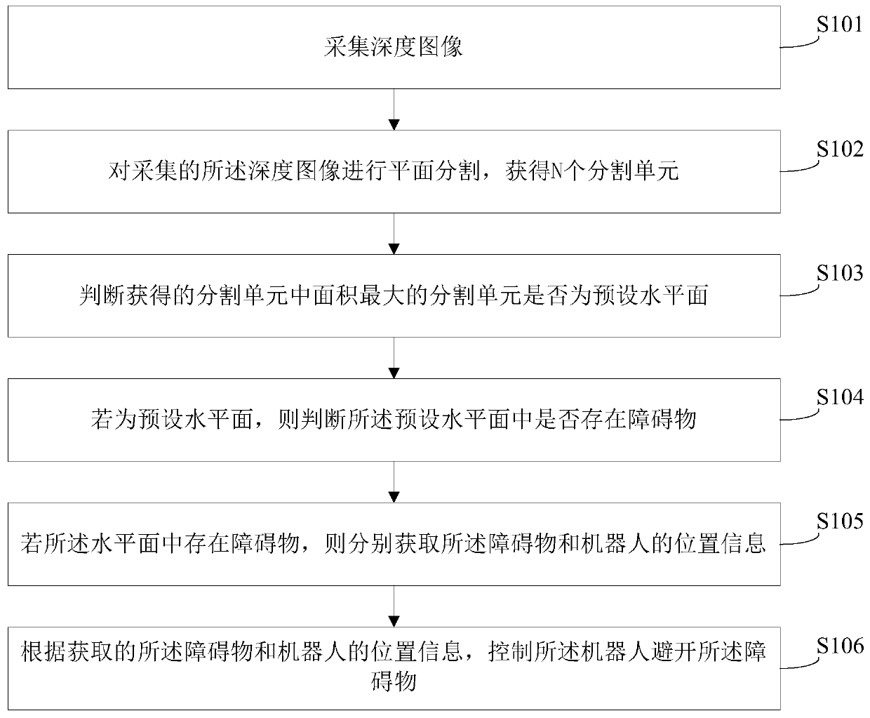
[0033] Figure 1-a It is a schematic flowchart of a method for robot obstacle avoidance provided in Embodiment 1 of the present invention, and the method may include the following steps:
[0034] S101: Collect a depth image.
[0035] Wherein, the robot is a device for automatically performing work, which can accept human commands and run pre-programmed programs, thereby achieving the purpose of assisting or replacing human work; compared with the plane image, the depth image also includes There is distance information from the frame grabber to the object.
[0036] In one embodiment, the robot is a mobile robot.
[0037] In one embodiment, the mobile robot is a wheeled mobile robot.
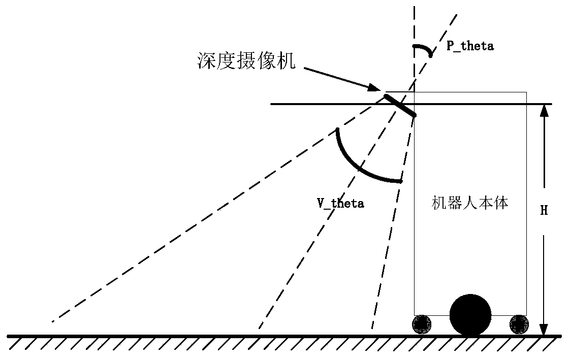
[0038] In one embodiment, the depth image may be collected by a visual sensor of the robot, such as a 3D depth camera. It should be understood that the depth image is an image in the camera coordinate system.
[0039] It should be noted that, in order to obtain a larger visual range and achiev...
Embodiment 2
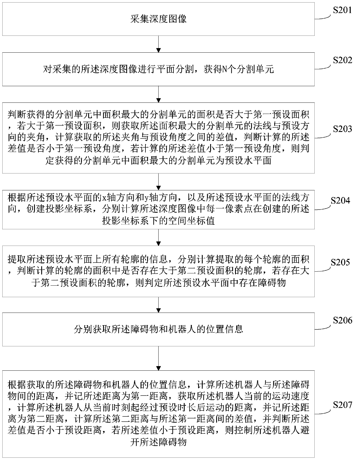
[0064] Figure 2-a The schematic flowchart of the method for robot obstacle avoidance provided in Embodiment 2 of the present invention is a further refinement and description of steps S103 and S104 in Embodiment 1 above. The method may include the following steps:
[0065] S201: Collect a depth image.
[0066] S202: Perform plane segmentation on the acquired depth image to obtain N segmentation units, where N is an integer greater than 1.
[0067] Wherein, the above steps S201-S202 are the same as the steps S101-S102 in the first embodiment, and the specific implementation process can refer to the description of the steps S101-S102, which will not be repeated here.
[0068] S203: Determine whether the area of the segment unit with the largest area among the obtained segment units is larger than the first preset area, and if it is larger than the first preset area, obtain the angle between the normal line of the segment unit with the largest area and the preset direction ,...
Embodiment 3
[0096] image 3 It is a schematic structural diagram of the robot provided in the third embodiment of the present invention. Such as image 3 As shown, the robot 3 of this embodiment includes: a processor 30 , a memory 31 and a computer program 32 stored in the memory 31 and operable on the processor 30 . When the processor 30 executes the computer program 32, the steps in the first method embodiment above are implemented, for example, steps S101 to S106 shown in FIG. 1 . Alternatively, implement the steps in the second method embodiment above, such as steps S201 to S207 shown in FIG. 2 .
[0097] The robot may include, but not limited to, a processor 30 and a memory 31 . Those skilled in the art can understand that, image 3 It is only an example of the robot 3 and does not constitute a limitation to the robot 3. It may include more or less components than shown in the illustration, or combine certain components, or different components. For example, the robot may also in...
PUM
 Abstract
Description
Claims
Application Information
 - R&D
- Intellectual Property
- Life Sciences
- Materials
- Tech Scout
- Unparalleled Data Quality
- Higher Quality Content
- 60% Fewer Hallucinations
Browse by: Latest US Patents, China's latest patents, Technical Efficacy Thesaurus, Application Domain, Technology Topic, Popular Technical Reports.
© 2025 PatSnap. All rights reserved.Legal|Privacy policy|Modern Slavery Act Transparency Statement|Sitemap|About US| Contact US: help@patsnap.com


