
Power transmission line sag on-line monitoring method and device

A technology for monitoring devices and transmission lines, applied in measuring devices, surveying and navigation, signal transmission systems, etc., can solve the problems of accuracy impact, high requirements for monitoring systems, unfavorable large-scale installation and monitoring, etc.

Inactive Publication Date: 2016-01-06
ZHENGZHOU XINGONG INTELLIGENT SYST CO LTD
View PDF3 Cites 30 Cited by
  • Summary
  • Abstract
  • Description
  • Claims
  • Application Information

AI Technical Summary

Problems solved by technology

[0003] At present, the sag monitoring methods of transmission lines mainly include: inclination measurement method, temperature measurement method, tension measurement method, radar ranging, laser ranging and image method, among which the temperature and tension measurement method needs to obtain the initial operating conditions of the overhead line, Relying on the state equation of the overhead line for calculation, and there are large errors in the change of the monitored environmental conditions. The monitoring methods of radar, laser ranging and inclination method are complicated, and have high requirements for the monitoring system. The cost is expensive, which is not conducive to large-scale Installation monitoring
None of the above measurement methods can realize real-time online measurement well, the measurement period is long, the efficiency is low, more manpower is required, and the accuracy will be affected. Therefore, it is necessary to find a simple and convenient monitoring method to realize the monitoring of transmission line overhead lines. Sag monitoring

Method used


Image

  • Power transmission line sag on-line monitoring method and device
  • Power transmission line sag on-line monitoring method and device
  • Power transmission line sag on-line monitoring method and device

Examples


Embodiment Construction

[0053] The technical solution of the present invention will be described in further detail below in conjunction with the accompanying drawings and embodiments.

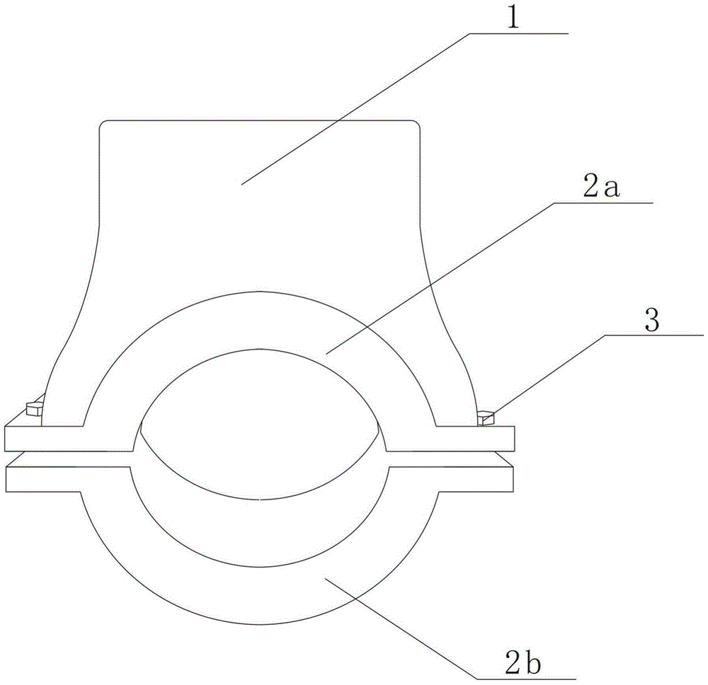
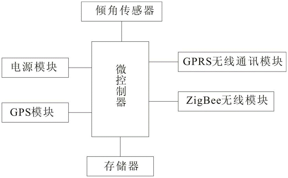
[0054] Such as figure 1 , 2 As shown, the transmission line sag online monitoring device includes an online monitoring device housing 1 and a fixing device fixed on the power transmission line. The fixing device includes a semicircular silicon steel sheet 2a, a semicircular silicon steel sheet 2b, two semicircular silicon steel sheets The two ends of the circular silicon steel sheet are connected by the connecting piece 3 to form a circular silicon steel sheet set on the transmission line. The connecting piece adopts bolts or screws. An induction coil is wound; the shell of the online monitoring device is set on the fixing device, and the shell is equipped with a microcontroller, an inclination sensor, a memory, a power supply module, a GPRS wireless communication module, a GPS module and a ZigBee wireless module. I...


PUM


Abstract

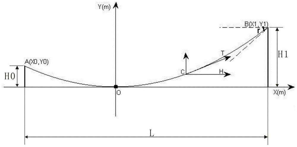
The invention discloses a power transmission line sag on-line monitoring method. The method includes: firstly installing an on-line monitoring device on the lead between two adjacent towers and close to one tower, using a laser range finder to measure the vertical distance from the tops of the two adjacent towers to the ground and the horizontal distance between the two adjacent towers, and recording data; energizing the power transmission line, and adopting a lead mutual inductance energy acquiring way for the on-line monitoring device; configuring the measured data into the on-line monitoring device by means of GPRS or a handset; measuring the inclination angle between one lead end and the horizontal plane by an inclination angle sensor; employing an accurate sag calculation method to calculate the height from the lowest point of the lead to the ground by a microcontroller in the on-line monitoring device; composing the position, sag, equation and inclination angle information into a data frame by the on-line monitoring device, and sending the data frame to a remote server or internet through GPRS. The method and device provided by the invention performs mathematical modeling on the power transmission line, accurately calculates the maximum sag value, and is conducive to on-line monitoring of the sag.

Description

technical field [0001] The invention relates to the technical field of power system monitoring, in particular to an online monitoring method and device for sag of a transmission line. Background technique [0002] Transmission line sag is the main indicator of line design and operation, which is related to the operation safety of the line, so it must be controlled within the scope specified in the design. The sag of the transmission line changes with the increase of the operating time and the change of the climate and the environment along the line. The change of the sag of the conductor of the transmission line will cause the safety distance of the conductor to the ground or to the cross object to fail to meet the requirements of the regulations, threatening the safe operation of the line. Even cause line failure, bring huge economic loss and personal safety threat to people's production and life. Therefore, the wire sag needs to be limited within a certain range, and the ...

Claims


Application Information

Patent Timeline
IPC IPC(8): G01C5/00G08C17/02
CPCG01C5/00G08C17/02
Inventor 丁英强王飞虎秦利涛武吉庆张毓琪
Owner ZHENGZHOU XINGONG INTELLIGENT SYST CO LTD
Learn More