Method for measuring mid-span deflection on the basis of bridge mid-span strain

A technology of strain measurement and mid-span deflection, applied in the direction of electric/magnetic solid deformation measurement, measuring device, electromagnetic measuring device, etc., can solve the problems of complex installation and calculation, difficult guarantee of sensor reliability and measurement accuracy, and high cost, and achieve The calculation method is simple, convenient for real-time online monitoring, and the effect of high reliability

Pending Publication Date: 2019-08-16
XIAMEN UNIV
View PDF0 Cites 5 Cited by
  • Summary
  • Abstract
  • Description
  • Claims
  • Application Information

AI Technical Summary

Problems solved by technology

However, in order to obtain the deflection of the bridge, this method needs to install multiple long-gauge fiber grating strain sensors at intervals between the upper and lower bridge decks between the two piers, and the bridge deflection can only be obtained through a relatively complicated calculation formula. There are also problems such as complex installation and calculation, high cost, and difficulty in ensuring sensor reliability and measurement accuracy.

Method used


Image

  • Method for measuring mid-span deflection on the basis of bridge mid-span strain
  • Method for measuring mid-span deflection on the basis of bridge mid-span strain
  • Method for measuring mid-span deflection on the basis of bridge mid-span strain

Examples


Embodiment Construction

[0032] In order to make the technical problems, technical solutions and beneficial effects to be solved by the present invention clearer and clearer, the present invention will be further described in detail below in conjunction with the accompanying drawings and embodiments.

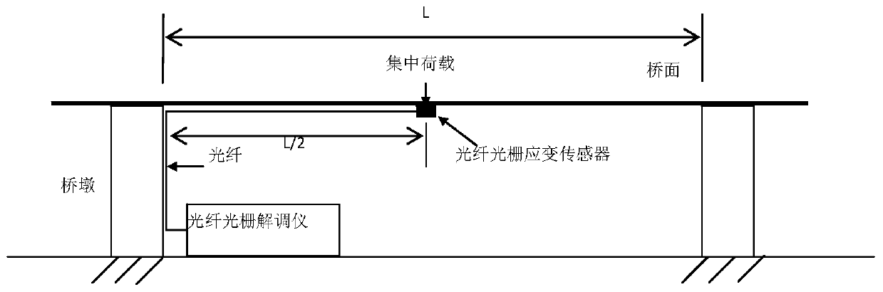
[0033] Such as figure 1 As shown, the embodiment of the present invention includes a strain sensor and a strain interrogator, the strain sensor adopts a fiber grating strain sensor, and the strain interrogator adopts an optical fiber grating interrogator;

[0034] The fiber grating strain sensor is installed at the bottom of the bridge span, and is used to measure the strain of the bridge longitudinal direction (vehicle running direction);

[0035] The fiber grating demodulator is connected to the fiber grating strain sensor through an optical fiber, and the fiber grating demodulator is installed at a certain position on the pier or on the ground.

[0036] In practical applications, the strain in the b...


PUM


Abstract

The invention discloses a method for measuring mid-span deflection on the basis of a bridge mid-span strain, and relates to the technical field of bridge deflection. The method comprises a strain sensor and a strain demodulation instrument, wherein the strain sensor is installed on the bottom of the bridge mid-span; and the strain demodulation instrument is connected with the strain sensor and isinstalled on a pier or the ground. The method for measuring the deflection comprises the following steps that: 1) applying a concentrated load to the bridge mid-span, and through the strain sensor andthe strain demodulation instrument, obtaining the bridge mid-span strain [Epsilon]L/2; 2) applying the concentrated load which is the same with 1) to the bridge mid-span, and measuring bridge mid-span strain WL/2; 3) substituting the strain and the deflection measured in 1) and 2) into WL/2=K[Epsilon]L/2 to solve a K value, wherein K is a coefficient; and 4) after the K value is calibrated, according to the [Epsilon]L/2 value measured by the strain sensor and the strain demodulation instrument and the above formula, carrying out calculation to obtain the mid-span deflection. The method has the advantages of being convenient and quick in obtaining the mid-span deflection, and can be widely applied to the measurement of the static and dynamic deflection of the bridge mid-span.

Description

technical field [0001] The invention relates to the technical field of bridge deflection detection, in particular to a method for measuring mid-span deflection based on bridge mid-span strain. Background technique [0002] Bridges are an important part of the transportation system, and their structural safety is related to social and economic development and people's personal safety. Among them, the deflection data of the bridge plays an important role in the health assessment of the bridge structure. The deflection data can directly reflect the vertical displacement of the bridge under the action of temperature, external load, wind and other factors, and have a great impact on the bearing capacity and stress loss of the bridge. and other aspects also play an important predictive role, which is a key parameter reflecting the basic characteristics of the bridge [1]. [0003] At present, the commonly used methods for measuring bridge deflection in engineering are as follows: ...

Claims


Application Information

Patent Timeline
Patent Type & Authority Applications(China)
IPC IPC(8): G01B11/16G01B7/16
CPCG01B7/16G01B7/18G01B11/165
Inventor 董小鹏卢梦楠关云卿
Owner XIAMEN UNIV
Why Eureka
Try Eureka