Array substrate, display panel, display device, and working method

An array substrate and display device technology, which is applied in the fields of array substrates, display panels and display devices, can solve the problems of decreased mechanical strength of the screen and occupying space in the display area, etc.

Inactive Publication Date: 2017-01-04
BOE TECH GRP CO LTD
View PDF4 Cites 28 Cited by
  • Summary
  • Abstract
  • Description
  • Claims
  • Application Information

AI Technical Summary

Problems solved by technology

[0003] However, the current terminal equipment is equipped with a separate hardware module for fingerprint recognition on the mobile phone. Obviously, for convenience, the hardware module is generally located outside the display area of ​​the screen, which not only takes up the space of the display area, but also Reduce the overall mechanical strength of the screen

Method used


Image

  • Array substrate, display panel, display device, and working method
  • Array substrate, display panel, display device, and working method
  • Array substrate, display panel, display device, and working method

Examples


Embodiment Construction

[0035] In order to make the technical problems, technical solutions and advantages to be solved by the present invention clearer, the following will describe in detail with reference to the drawings and specific embodiments.

[0036] The present invention provides a solution to the problem that a terminal device in the prior art needs to set a hardware module with a fingerprint identification function on the outside.

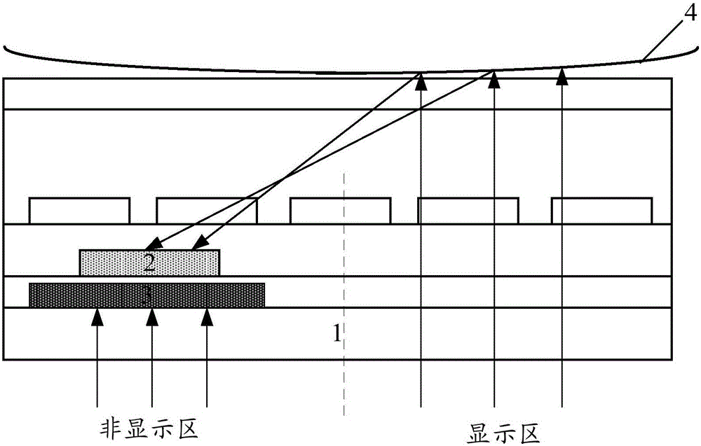
[0037] On the one hand, an embodiment of the present invention provides an array substrate, including a plurality of sub-pixel regions formed on the base substrate, such as figure 1 As shown, each sub-pixel area includes a display area and a non-display area for displaying images;

[0038] Wherein, the non-display area is provided with an optical sensing element 2 and an opaque pattern 3 located between the optical sensing element 2 and the base substrate 1 . The optical sensing element 2 can convert the received optical signal into an electrical signal, and th...


PUM


Abstract

The invention provides an array substrate, a display panel, a display device, and a working method. The array substrate comprises: a plurality of sub-pixel regions on a substrate. Each sub-pixel region includes a display area for displaying a frame and a non-display area. The non-display area is provided with an optical sensing element. The sensing element is capable of converting a received optical signal into an electrical signal. The non-display area is further provided with an opaque pattern between the optical sensing element and the substrate. The positive projection, on the substrate, of the opaque pattern completely covers the positive projection, on the substrate, of the optical sensing element. A fingerprint recognition function is realized inside a terminal screen, thereby improving the user experience.

Description

technical field [0001] The invention relates to the display field, in particular to an array substrate, a display panel, a display device and a working method. Background technique [0002] With the rapid development of mobile communication technology and smart terminals, fingerprint verification technology is used by a wider range of people and has become a part of our lives. At present, people can realize very practical functions such as terminal unlocking and fast payment through fingerprint verification. [0003] However, the current terminal devices are all equipped with a hardware module for fingerprint recognition on the mobile phone. Obviously, for convenience, the hardware module is generally located outside the display area of ​​the screen, which not only takes up the space of the display area, but also Decrease the overall mechanical strength of the screen. [0004] In view of this, if the fingerprint recognition function can be implemented on the display area o...

Claims


Application Information

Patent Timeline
Patent Type & Authority Applications(China)
IPC IPC(8): G06K9/00G02F1/1333
CPCG02F1/13338G06V40/1318
Inventor 李忠孝
Owner BOE TECH GRP CO LTD
Why Eureka
Try Eureka