
Method and system for reactive power coordination control

A technology of coordinated control and power distribution, applied in the direction of reactive power adjustment/elimination/compensation, reactive power compensation, etc., can solve the problems of sacrificing control accuracy, unable to achieve control target without deviation control, etc., to achieve sacrificing control accuracy, improve The effect of system fault tolerance and simple human-machine interface

Inactive Publication Date: 2017-01-04
CHINA SOUTHERN POWER GRID COMPANY +2
View PDF4 Cites 0 Cited by
  • Summary
  • Abstract
  • Description
  • Claims
  • Application Information

AI Technical Summary

Problems solved by technology

However, this method cannot achieve the unbiased control of the control target at the expense of control accuracy

Method used


Image

  • Method and system for reactive power coordination control
  • Method and system for reactive power coordination control

Examples


Embodiment 1

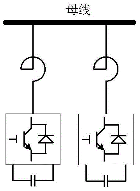
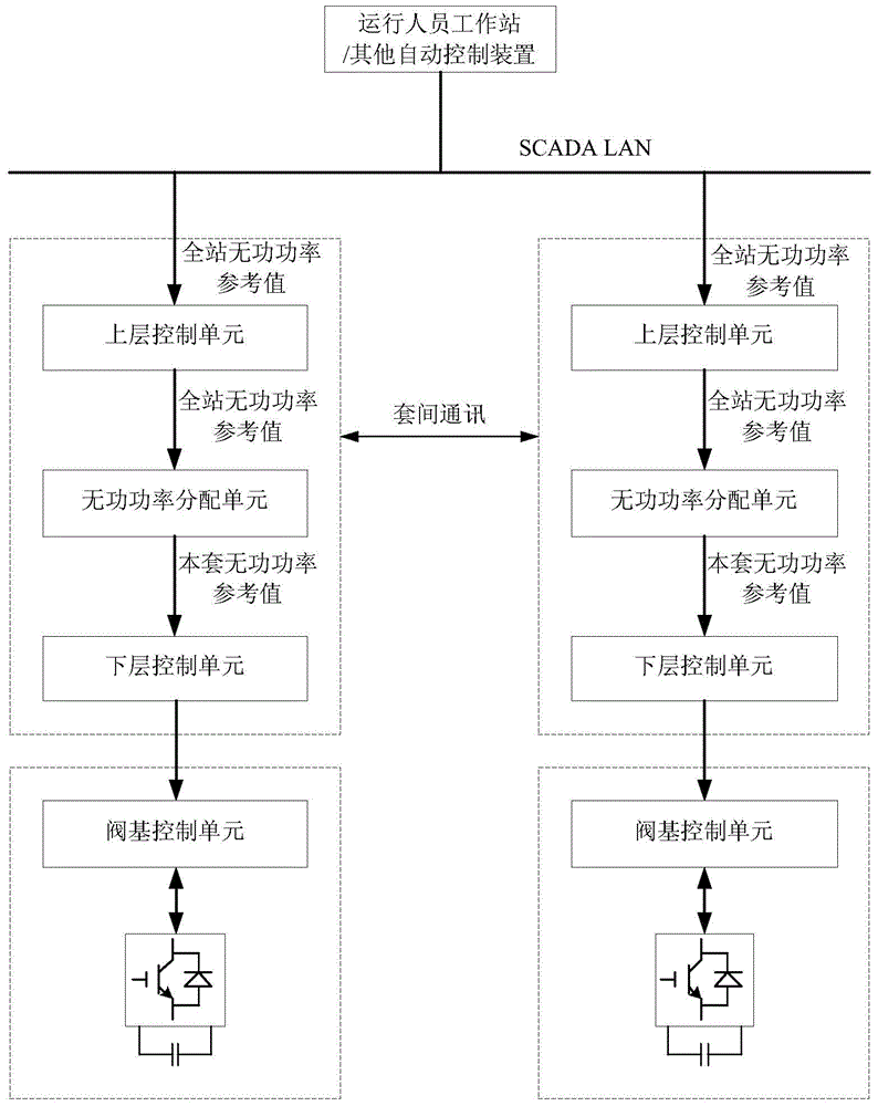
[0033] see figure 1 with figure 2 , the reactive power coordinated control method includes the following steps:

[0034] At least two sets of reactive power compensation equipment run in parallel;

[0035] Each set of reactive power compensation equipment is equipped with the same controller;

[0036] Each set of controllers includes at least an upper control unit, a reactive power distribution unit and a lower control unit;

[0037] Inter-suite communication is configured between each set of controllers, one of which is the main controller, and the other sets are standby controllers; the state of the upper control unit of the standby controller follows the state of the upper control unit of the main controller. When the main controller fails One of the backup controllers is automatically upgraded to the master controller, and the faulty controller is downgraded to the backup controller.

[0038] Further, the above-mentioned upper control unit includes at least an AC volt...

Embodiment 2

[0044] see figure 1 with figure 2 , the reactive power coordinated control system includes at least two sets of reactive power compensation equipment running in parallel; each set of reactive power compensation equipment is equipped with the same controller; each set of controllers includes at least the upper control unit, reactive power distribution sheet and The lower control unit; each set of controllers is configured with inter-suite communication, one of which is the master controller, and the other sets are standby controllers. The state of the upper control unit of the standby controller follows the state of the upper control unit of the master controller. When the main controller fails, one of the backup controllers is automatically upgraded to the main controller, and the faulty controller is reduced to the backup controller.

[0045] Further, the above-mentioned upper control unit includes at least an AC voltage control module and a reactive power control module, t...


PUM


Abstract

The invention discloses a method for reactive power coordination control. The method includes following steps: two sets of reactive compensation devices operate in parallel; each reactive compensation device is provided with the same controller; each controller comprises an upper layer control unit, a reactive power distribution unit, and a lower layer control unit, communication is configured between the two controllers, one is a main controller, and the other is a standby controller; and the state of the upper layer control unit of the standby controller follows the state of the upper layer control unit of the main controller, and when the main controller has a fault, the standby controller is automatically upgraded as the main controller, and the controller with fault is degraded as the standby controller. The invention discloses a reactive power coordination control system. According to the method and system, the problem of the increase of the hardware cost brought by additional installation of the upper layer controller can be avoided, the controllers of the two sets of reactive compensation devices are standby controllers for each other, the system fault tolerance is improved, no-deviation control can be realized, and the control precision is not influenced.

Description

technical field [0001] The invention belongs to the technical field of power electronics, and in particular relates to a method and system for coordinated control of reactive power. Background technique [0002] Power quality has an important impact on the power supply security and power supply quality of the power grid. The reactive power compensation device can provide the necessary reactive power compensation to the grid, stabilize the grid voltage, and is more and more widely used in the power system. However, limited by the capacity of the device, a single set of reactive power compensation device sometimes cannot meet the needs of the grid for reactive power. Compensation devices run in parallel. [0003] When the reactive power compensation device takes the total station AC voltage or power factor as the control target, since the control targets of the two sets of reactive power compensation devices are the same, the reactive power will oscillate between the two set...

Claims


Application Information

Patent Timeline
IPC IPC(8): H02J3/18
CPCY02E40/30
Inventor 丁久东田杰董云龙李钢胡兆庆卢宇朱韬析余江
Owner CHINA SOUTHERN POWER GRID COMPANY
Learn More