
Charging method and device

A charging method and a charging device technology, applied in the electronic field, can solve the problems of terminal heat sensitivity, affecting user experience, and high charging power, and achieve the effects of improving user satisfaction, enhancing product competitiveness, and improving charging speed.

Inactive Publication Date: 2017-01-04
QIKU INTERNET TECH SHENZHEN CO LTD
View PDF3 Cites 14 Cited by
  • Summary
  • Abstract
  • Description
  • Claims
  • Application Information

AI Technical Summary

Problems solved by technology

[0004] Although the charging speed of fast charging is fast, due to the high charging power, the terminal generates a lot of heat, especially when the terminal is in the state of charging and using, the problem of terminal heating is more prominent. It is also more sensitive. If the heat is too severe, it will greatly affect the user experience

Method used


Image

  • Charging method and device
  • Charging method and device
  • Charging method and device

Examples


Embodiment 1

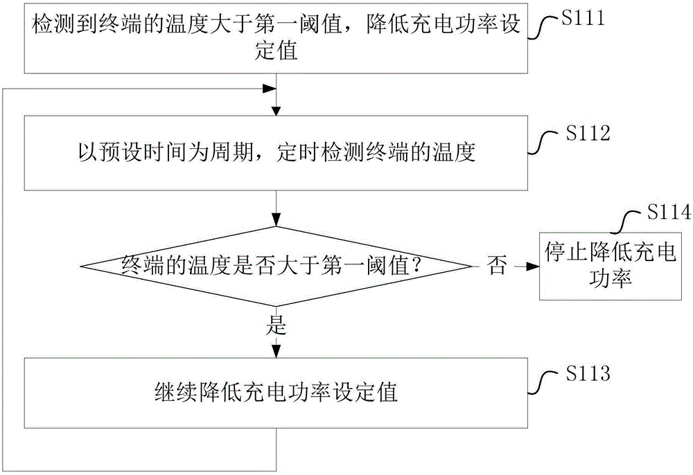
[0080] refer to figure 1 , propose the charging method of the first embodiment of the present invention, the method includes the following steps:

[0081] S11. Detect the temperature of the terminal during the charging process.

[0082] Specifically, when it is detected that the charging interface of the terminal is connected to the charger and enters the charging state, the temperature of a specific part of the terminal is detected in real time or periodically (periodically) by the temperature sensor. The specific part is usually a part with serious heat generation or a part that the user is more sensitive to temperature, of course, any part can also be designated as required.

[0083] Optionally, any one of the terminal's battery, screen, central processing unit (Central Processing Unit, CPU), power management unit (Power Management Unit, PMU), graphics processor (Graphic Processing Unit, GPU) and other parts can A temperature sensor is arranged at the position, and the te...

Embodiment 2

[0155] refer to Figure 7 , propose a charging device according to the second embodiment of the present invention, the charging device includes a temperature detection module 10 and a charging strategy module 20, wherein:

[0156] Temperature detection module 10: for detecting the temperature of the terminal during charging.

[0157] Specifically, when it is detected that the charging interface of the terminal is connected to the charger and enters the charging state, the temperature detection module 10 detects the temperature of a specific part of the terminal in real time or periodically (periodically) through the temperature sensor. The specific part is usually a part with serious heat generation or a part that the user is more sensitive to temperature, of course, any part can also be designated as required. After detecting the temperature data, the temperature detection module sends the detected data to the charging strategy module.

[0158] Optionally, a temperature sen...


PUM


Abstract

The invention discloses a charging method and device. The charging method comprises the following steps: detecting the temperature of a terminal during charging; performing a first charging strategy when the temperature is greater than a first threshold; performing a second charging strategy when the temperature is smaller than a second threshold; wherein the first threshold is greater than the second threshold. According to the charging method provided by the embodiment of the invention, by setting the first threshold and the second threshold of the terminal temperature, different charging strategies are executed according to a change of temperature in the charging process to adjust the charging power of the terminal so that the temperature of the terminal is maintained in a suitable range between the first threshold and the second threshold, the user experience cannot be affected due to too high terminal temperature, and the charging speed cannot be reduced due to too low charging power, thereby the user experience is improved on the basis of ensuring the charging speed, so that the charging speed and the user experience are taken into account to improve the user satisfaction degree and enhance the competitiveness of products.

Description

technical field [0001] The invention relates to the field of electronic technology, in particular to a charging method and device. Background technique [0002] As the mobile terminal has more and more functions, its power consumption is also increasing, which seriously affects the battery life of the terminal. In order to solve the problem of high power consumption of the terminal, two technical solutions are mainly adopted at present: one is to manage the power saving of each application in the terminal to avoid unnecessary power consumption and reduce power consumption; the other is to improve Battery capacity, so that more power can be stored. [0003] At present, the battery capacity of mobile terminals is getting higher and higher. If the traditional charging method is continued, it will take a long time to fully charge the battery. For this reason, a fast charging scheme (referred to as fast charging) is proposed in the prior art, and fast charging is to use higher ...

Claims


Application Information

Patent Timeline
IPC IPC(8): H02J7/00H01M10/44H01M10/48
CPCH01M10/443H01M10/486H02J7/007H02J7/0091Y02E60/10
Inventor 张哲
Owner QIKU INTERNET TECH SHENZHEN CO LTD
Learn More