

Detection method of radio frequency path and mobile terminal
A radio frequency channel, mobile terminal technology, applied in the field of communication, can solve the problem that the radio frequency circuit can't feedback in time
- Summary
- Abstract
- Description
- Claims
- Application Information
AI Technical Summary
Problems solved by technology
Method used
Image

Examples
no. 1 example
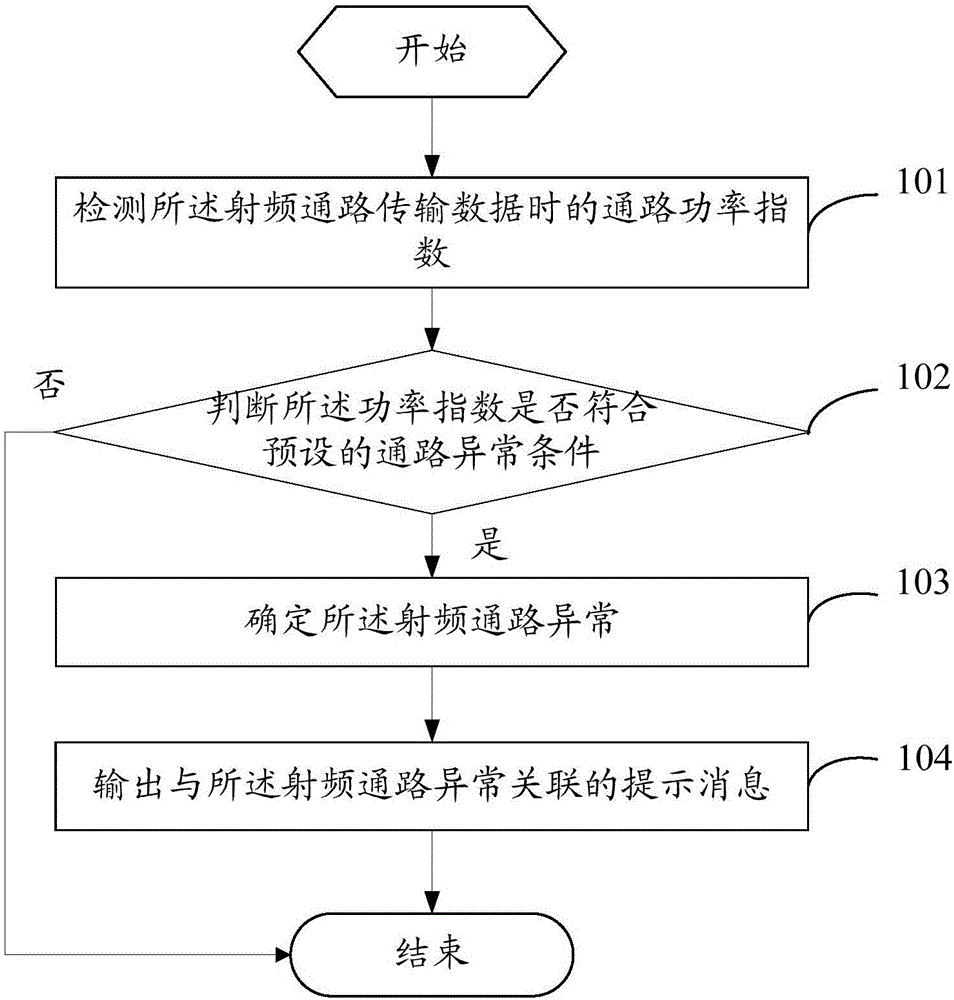
[0030] see figure 1 , figure 1 is a flow chart of a radio frequency path detection method provided by an embodiment of the present invention, such as figure 1 As shown, the first embodiment of the present invention is used for a mobile terminal with a radio frequency path, and its radio frequency path detection method includes the following steps:
[0031] Step 101. Detect the power index when the radio frequency channel transmits data.
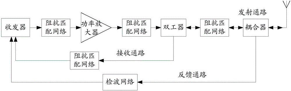
[0032] In this step, the power index is the power index when the radio frequency path is working, and the power index is a reference index for evaluating power, which can be a transmission power index or a feedback power index; it can also be a power index on any branch of the radio frequency path, as long as The power index on the branch can be calculated by the above-mentioned feedback power index or transmit power index, for example, as figure 2 As shown, what is detected is the power index at the output end of the RF path power amplif...
no. 2 example
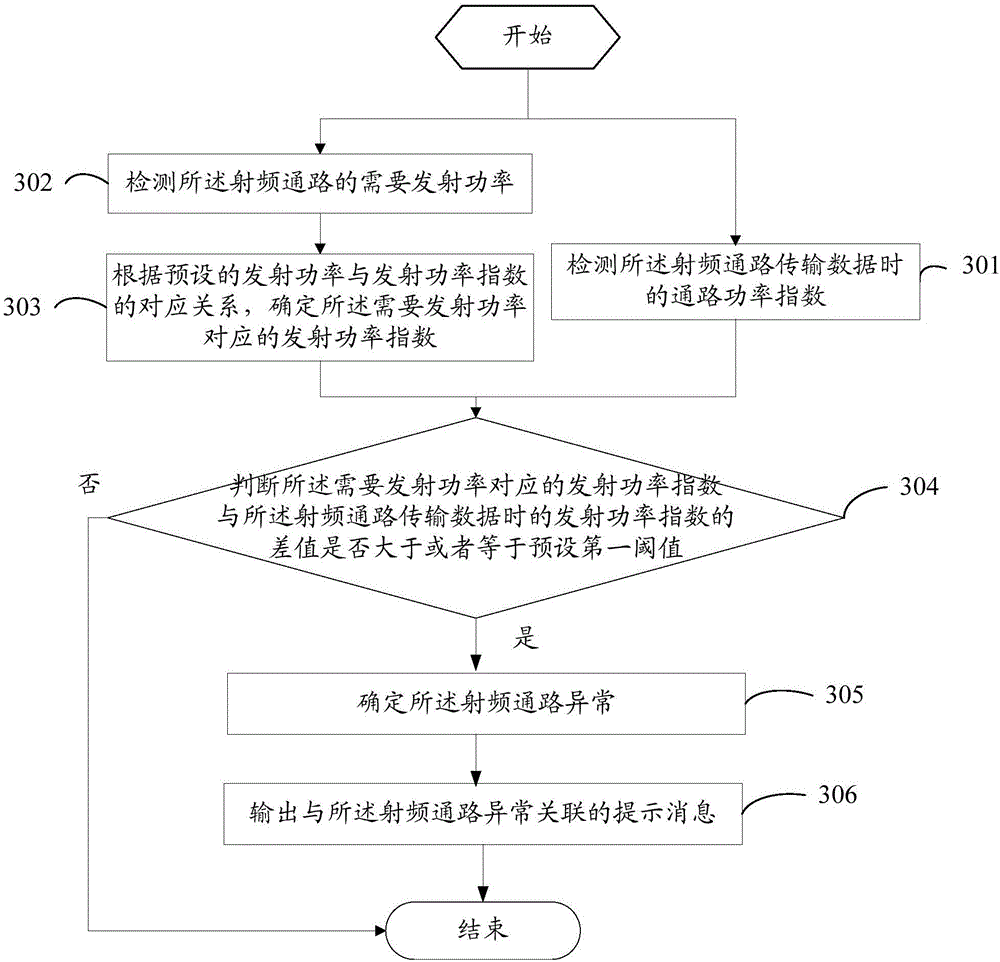
[0042] see image 3 , image 3 A flow chart of another radio frequency channel detection method provided by an embodiment of the present invention, the power index is the transmission power index when the radio frequency channel transmits data, such as image 3 shown, including the following steps:
[0043] Step 301. Detect the power index when the radio frequency channel transmits data.
[0044] In this step, the power index is the power index when the radio frequency path is working, and the power index is a reference index for evaluating power, which can be a transmission power index or a feedback power index; it can also be a power index on any branch of the radio frequency path, as long as The power index on the branch can be calculated by the above-mentioned feedback power index or transmit power index, for example, as figure 2As shown, what is detected is the power index at the output end of the RF path power amplifier, which can be obtained by calculating the trans...
no. 3 example
[0067] see Figure 4 , Figure 4 A flow chart of another radio frequency path detection method provided by an embodiment of the present invention, the power index is the feedback power index when the radio frequency path transmits data, such as Figure 4 shown, including the following steps:
[0068] Step 401. Detect the power index when the radio frequency channel transmits data.
[0069] In this step, the power index is the power index when the radio frequency path is working, and the power index is a reference index for evaluating power, which can be a transmission power index or a feedback power index; it can also be a power index on any branch of the radio frequency path, as long as The power index on the branch can be calculated by the above-mentioned feedback power index or transmit power index, for example, as figure 2 As shown, what is detected is the power index at the output end of the RF path power amplifier, which can be obtained by calculating the transmit po...
PUM
 Abstract
Description
Claims
Application Information