Clamping hand device for casing sleeve shrinkage continuous production and automatic casing sleeve shrinkage machine

A technology of shrinking machine and casing, which is applied in the field of gripper device and automatic casing shrinking machine, can solve the problems of easy air leakage, can not realize the switching of air flow, etc., and achieve the effect of stable air pressure

Active Publication Date: 2017-01-11
FOSHAN VEHICIAN LNTELLIGENT EQUIP CO LTD
View PDF8 Cites 2 Cited by
  • Summary
  • Abstract
  • Description
  • Claims
  • Application Information

AI Technical Summary

Problems solved by technology

[0002] In the continuous shrinking production equipment for casings, there is a hollow smooth core tube (shrinking rod) in the middle of the casing to support the folded casing to have a circular inner hole. The casing before the shrinking mechanism is inflated, so that the casing expands into a cylindrical shape and enters the folding mechanism. The shrunk casing will be pushed forward along the shrinking rod, and will be cut by the dividing mechanism after reaching the set number of meters. The moving clamp mechanism is brought to the feeding rod connected to the shrinking rod. When the whole section of shru...

Method used


Image

  • Clamping hand device for casing sleeve shrinkage continuous production and automatic casing sleeve shrinkage machine
  • Clamping hand device for casing sleeve shrinkage continuous production and automatic casing sleeve shrinkage machine
  • Clamping hand device for casing sleeve shrinkage continuous production and automatic casing sleeve shrinkage machine

Examples


Embodiment Construction

[0017] The following will clearly and completely describe the technical solutions in the embodiments of the present invention with reference to the accompanying drawings in the embodiments of the present invention. Obviously, the described embodiments are only some, not all, embodiments of the present invention. Based on the embodiments of the present invention, all other embodiments obtained by persons of ordinary skill in the art without making creative efforts belong to the protection scope of the present invention.

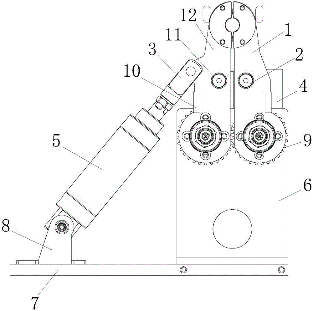
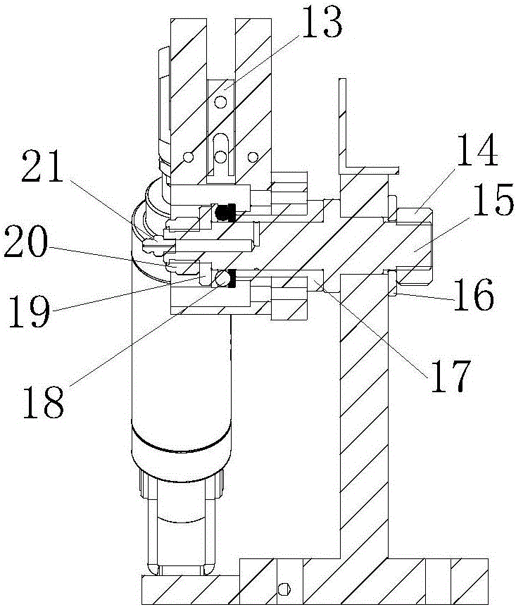
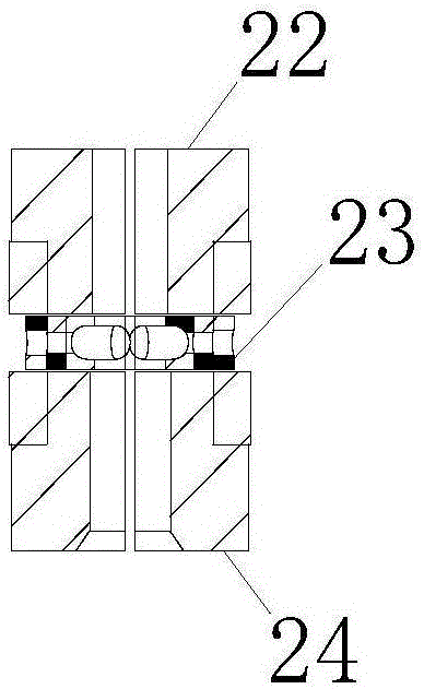
[0018] see Figure 1-6 , in the embodiment of the present invention, a hand clamping device for continuous casing shrinking production and an automatic casing shrinking machine, including a cylinder bottom plate 7, the top of the cylinder bottom plate 7 is provided with a B clamp seat 6 and a cylinder seat 8, and the B clamp seat 6 A gear 9 is installed through a gear shaft 15. The number of gears 9 is 2. The two gears 9 mesh and rotate in reverse synchronousl...


PUM


Abstract

The invention discloses a clamping hand device for casting continuous sleeve shrinkage production and an automatic casing sleeve shrinkage machine. The clamping hand device comprises a cylinder baseplate, a clamping seat B and a cylinder seat are arranged at the top of the cylinder baseplate, a gear is mounted on the clamping seat B through a gear shaft, a left swing arm and a right swing arm are arranged on the gear, an air replenishing clamp rotating pin and an air replenishing clamp limiting plate are arranged on each of the left swing arm and the right swing arm, an approach switch seat is arranged on the other sides of the left swing arm and the right swing arm, and a first clamping piece and a second clamping piece are arranged at the tops of the left swing arm and the right swing arm. When a cylinder pushes the left and right swing arms to close through a Y-shaped joint, an air replenishing clamping arm is driven to close, a groove exactly aligns at a circle of ventilation holes in the side wall of a piston valve so as to fill a sleeve shrinkage rod with air without leaking, stability in air pressure inside a casing is ensured, the sleeve shrinkage rod is firmly clamped, the side wall of a piston is annularly sealed, and a circle of small holes in the side wall of the piston are inflated without air leaking.

Description

technical field [0001] The invention relates to the technical field of shrinking packaging of casings and film sleeves, and in particular to a hand clamping device for continuous shrinking production of casings and an automatic casing shrinking machine. Background technique [0002] In the equipment for continuous shrinking production of casings, there is a hollow smooth core tube (shrinking rod) in the middle of the casing to support the shrunken casings to have a circular inner hole. The casing before the shrinking mechanism is inflated, so that the casing expands into a cylindrical shape and enters the folding mechanism. The casing that has been folded will be pushed forward along the set of shrinking rods. After reaching the set number of meters, it will be cut by the dividing mechanism. The moving clamp mechanism is brought to the feeding rod connected to the shrinking rod. When the whole section of shrunk casing is passed into the feeding rod, the feeding rod will be s...

Claims


Application Information

Patent Timeline
IPC IPC(8): A22C13/02
CPCA22C13/02
Inventor 莫少难
Owner FOSHAN VEHICIAN LNTELLIGENT EQUIP CO LTD
Why Eureka
Try Eureka